-By Shri Rajneesh Saroj, GM (Civil)/NHSRCL
Abstract: The Mumbai-Ahmedabad High-Speed Rail project represents a pioneering effort by the Ministry of Railways to introduce high-speed trains in India. Central to this monumental initiative is the construction of the underground station at Mumbai's Bandra Kurla Complex (BKC), a project marked by significant engineering and environmental challenges.
The excavation activities at BKC, located in the heart of the city, necessitate adherence to stringent environmental norms due to the substantial air and noise pollution generated. Innovative solutions, such as the deployment of mist guns for dust suppression and continuous water sprinkling, have been implemented to mitigate air pollution. Additionally, 5-meter-high barriers have been erected to reduce noise pollution from piling and excavation work. Real-time monitoring of the Air Quality Index (AQI) ensures that air quality remains superior to that in nearby areas, reflecting a commitment to environmental management.
To address the inherent risks of deep excavation, a comprehensive ground support system incorporating secant piles, soil anchors, and walers has been employed. The secant piles are designed to limit ground movement of nearby buildings to 10 mm or 0.5% of the excavation height, whichever is lower. Full-scale trial anchors are tested to ensure design adequacy, with instrumentation such as inclinometers and piezometers monitoring the system's performance.
This paper details the methodologies and technologies applied to manage environmental impacts and ensure structural integrity during the excavation and construction phases at BKC. The integration of rigorous monitoring and innovative engineering solutions highlights the project's commitment to safety, sustainability, and adherence to regulatory standards, setting a precedent for future infrastructure projects in metropolitan settings.
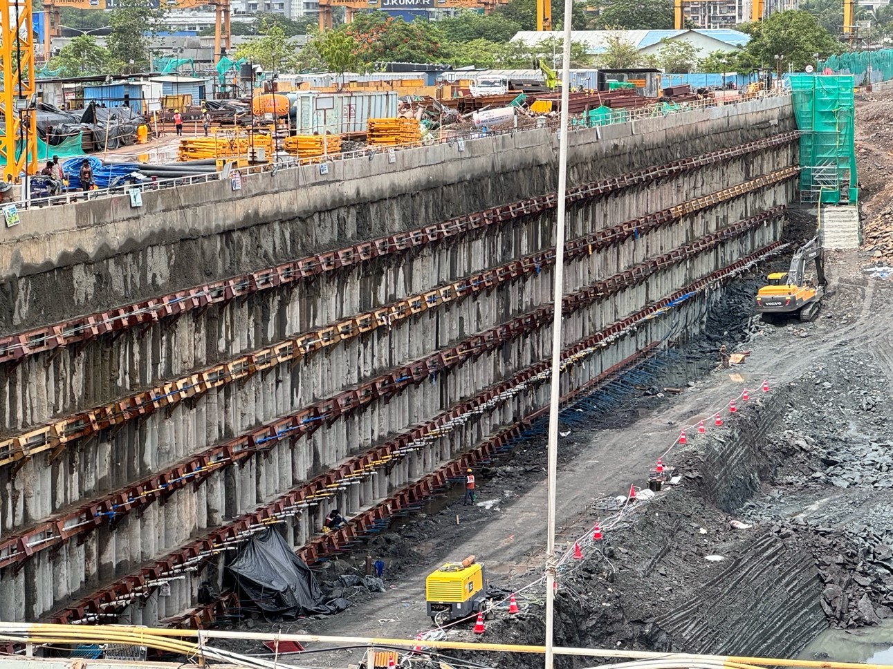
Figure 1: Secant Piles, Soil Anchors and walers
The Mumbai-Ahmedabad High-Speed Rail project marks the Ministry of Railways' pioneering effort to introduce high-speed trains in India. Among the monumental civil structures being erected along the proposed Mumbai-Ahmedabad corridor is the underground station at Mumbai's Bandra-Kurla Complex (BKC)
The underground station at BKC will be one of its kind. It will have six underground platforms, each 450 meters in length, capable of accommodating a 16-car train. The station building will comprise three levels: the bottom floor (3rd basement) will house the platforms, the 2nd basement will be designated for the concourse area, ticketing, and business class facilities, and the 1st basement will be for back-of-the-office services.
The construction of this iconic station involves digging vertically to a depth of 32 meters. Given the area's significance and proximity to surrounding structures, any construction mishaps are intolerable. The station primarily extends in an east-west direction, spanning 1,030 meters in length. Its width varies, with the western end measuring 70 meters and the eastern end 40 meters. To safeguard against any slope failure due to deep excavation, a ground support system consisting of 3,388 secant piles of 800 and 1,000 mm diameter, soil anchors, struts, and walers is being installed in a grid pattern with horizontal intervals of 1,300 mm and 2,600 mm and vertical intervals of 3,000 mm and 2,500 mm. Along the perimeter, on the vertical face of the secant piles to the socketing depth, rock bolting is done with help of rock bolts of 6000mm to 8000m in a grid pattern depending on rock mapping. It forms a protective barrier to absorb the lateral earth
Deep excavation poses inherent risks of bank failure, necessitating vigilant monitoring of ground movements. Mitigation occurs in two stages: first, by designing a support structure comprising secant piles with soil anchoring arrangements, and second, by monitoring its effectiveness.
During the design stage, rigorous checks are implemented. The contractor’s Detailed Design Consultant (DDC) initiates the design, followed by proof-checking by their consultant, and a final review by our team of engineers.
Execution entails thorough quality checks and continuous monitoring. Instrumentation plays a pivotal role in monitoring the performance of the support system, especially given the proximity to crucial structures like the Metro Line 2B and office buildings.
- Metro-2B Adjacent Piers
The construction of the high-speed rail (HSR) station within Mumbai's Bandra due to its proximity to the Metro Line 2B alignment. Two Metro-2B stations, ILFS and MTNL, fall within the influence zone of the HSR station, and construction of HSR station and Metro . Of particular concern is the ILFS station, situated a mere 5 meters laterally from the HSR station for a stretch of 185 meters(station length). Coordinating simultaneous construction projects posed a significant challenge for engineers, necessitating the design of a ground support system that operates seamlessly with the Metro work to prevent adverse effects.
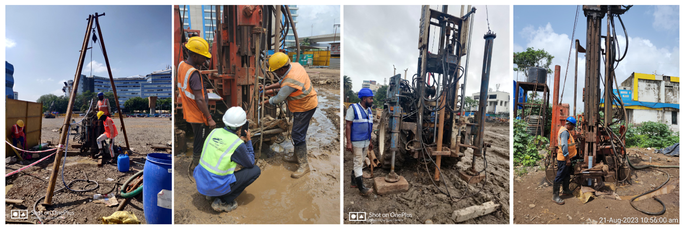
Figure 2: Geotechnical Investigation in Progress
- SCLR Flyover Adjacent Piers
The Santacruz Chembur Link Road (SCLR) flyover intersects the HSR alignment at the eastern end, requiring careful integration during construction. While the flyover's foundations have been strategically placed to avoid interference, this area presents additional challenges due to its proximity to the Mithi River and the predominantly filled soil with poor geotechnical properties.
The risk mitigation comes in three stages. Starting the design with consideration of all adverse combinations of failure, followed by execution of the system with proper quality, and finally monitoring by sufficient instrumentations. The ground support system adopted for this project was consist of secant piles, soil anchors, walers and rock bolts. The flow of all the process is as under
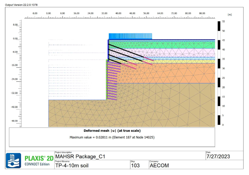
Figure 3: Screenshot from Plaxis 2D software
All the design parameters are decided after extensive Geotechnical investigation. For the Underground station 37 number of bore holes were done to a depth of ranging from 40 m to 95 m access the details of the strata. 24 nos of bore holes are done around the periphery and remaining bores are done in middle. Therefore roughly at every 100m the soils profile is available to the designer. These details were basis for design of the ground support system.
The ground support system is designed for Dead Load, Hydrostatic pressure load, Heavy Construction Equipment and surcharge load, seismic load, and TBM load. Plaxis 2D software is used for analysis and overall stability of the system.
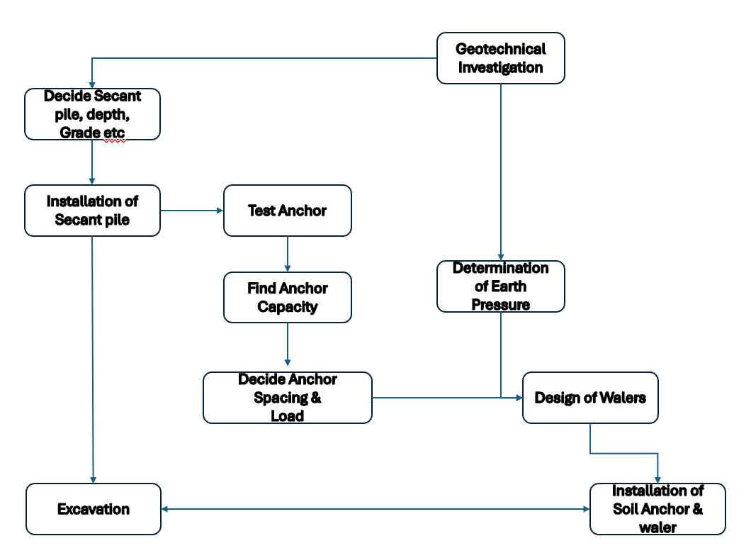
Figure 4: Flowchart for the Excavation
The drilling for secant piles is carried out using a rotary type drilling rig. The secant piles are terminated with a 1-meter embedment in Type-III rock, as determined by the geotechnical investigation. The piles are cast in a series of hard (RCC) and soft (PCC) segments, placed alternately. The concreting method is the same as for any other pile used in bridge or building foundations.
The design parameters for the secant piles are as follows:
- Concrete Strength (Hard Pile): M-35
- Concrete Strength (Soft Pile): M-15
- Diameter: 800 mm & 1000 mm
- Spacing (Hard to Soft): 650 mm
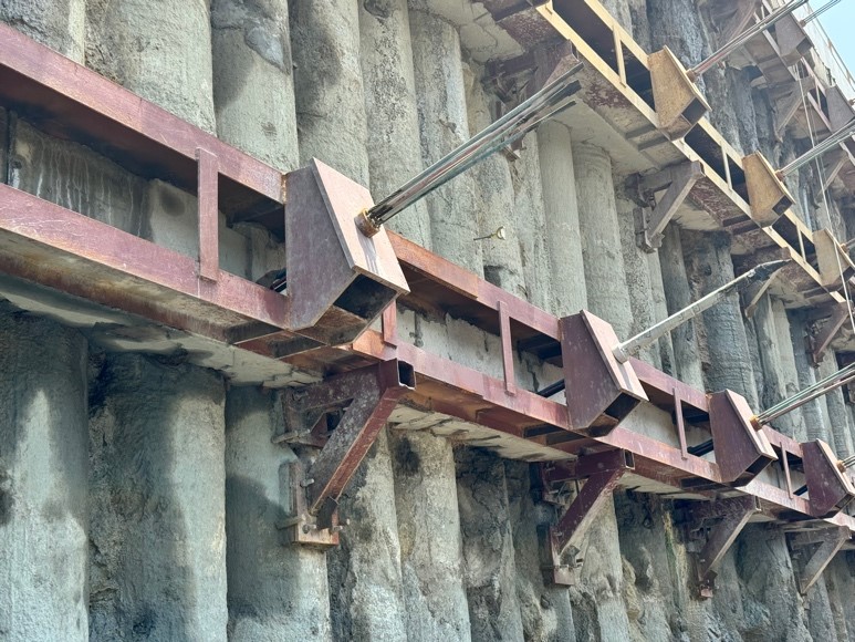
Figure 5: Walers, Soil Anchors
However, the concrete strength considered in the design was only 80%, accounting for the tremie concrete. Geotechnical investigations were conducted every 100 meters, while confirmatory boreholes to ascertain the type of rock were done every 10 meters. Criteria were established for the identification of Type-III rock and termination of piles: a pile can be terminated at a level where the rate of penetration is less than 20 mm/min at 120 bar pressure. The deepest pile in the station is 21.2 meters, and the shallowest pile is 10.8 meters. The summary of various pile depths achieved as per the above criteria is as follows:
| S.N | Range (m) | Number of Piles |
|---|---|---|
| 1 | 10-12 | 77 |
| 2 | 12-14 | 1134 |
| 3 | 14-16 | 1165 |
| 4 | 16-18 | 746 |
| 5 | 18-20 | 211 |
| 6 | 20-22 | 55 |
Table 1: Summary of Pile Depth
After the installation of secant piles, they were tied together with a capping beam of 1m x 1m or 1.2m x 1m at the top, and excavation was carried out. Soil anchors and walers were provided at the required levels along with the excavation, as per the design.
Soil anchors and walers are integral parts of the ground support system when a deep vertical cut.
The design of soil anchors is done in two parts. In the first part, the Ground Investigation Report determines the earth pressure and accordingly decides the force to be applied through the soil anchor to counteract the lateral earth pressure.
In the second part, the soil anchors are designed to provide the desired anchor capacity. This capacity depends on factors such as ground/grout interface resistance, fixed and free length, length of the anchor, diameter of the strand, and other vendor-specific parameters. For instance, some vendors use an additional compression element (generally a steel element) that transfers force from the strand to the cement grout. Anchor capacity depends on the combined effect of all these parameters.
A typical detail of anchor is shown in the pic below
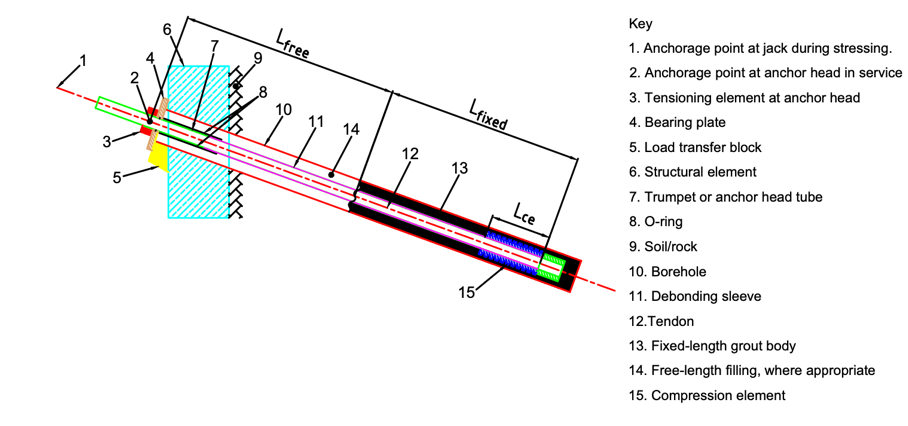
Figure 6: Details of Soil Anchor
Full-scale trial/test anchors are employed to demonstrate the behavior and performance of proposed anchors. This process ensures quality and verifies the adequacy of the design. These tests are referred to as investigation tests in BS 8081:2015. The designer uses the results obtained from these investigation tests, specifically the anchor capacity, to determine the anchor spacing, orientation, and individual anchor loads.
To carry out a test anchor, an anchor along with a waler is installed in a secant pile at a pre-determined location. The anchor is stressed until the breaking point, and the breaking load is recorded. A minimum of three anchors are tested, and the lowest breaking load is considered the ultimate capacity of the anchor. Further, only 70% of this value is considered the design tensile capacity, in line with the provisions of IS-10270 Clause 5.1.
Details of the test anchor and the results of the investigation test are reproduced below:
TABLE INDICATING TEST ANCHORS AND ANCHOR CAPACITY
| S. N. | TEST ANCHOR ID | LEVEL | PILE ID | NO. OF STRAND AND DIA | FIXED LENGTH (M) | FREE LENGTH (M) | TOTAL LENGTH (M) | GUTS (KN) | ANCHOR CAPACITY |
|---|---|---|---|---|---|---|---|---|---|
| 1 | SF-01 | (+)2.04 | SP-773 | 4nos/ 15.2 Dia | 6 | 27.3 | 33.3 | 1036 | 725 (70% OF GUTS) |
| 2 | SF-04 | (-)3.96 | SP-777 | 8nos/ 15.2 Dia | 12 | 13.1 | 25.1 | 2072 | 1451 ( 70 % OF GUTS) |
| 3 | SF-06 | (-)3.96 | SP-817 | 6nos/ 15.2 Dia | 6 | 13.1 | 19.1 | 1554 | 975 ( 62.7 % OF GUTS) |
| 4 | CC-08 | (+)2.04 | SP-891 | 3nos/ 12.2 Dia | 6 | 22.4 | 28.4 | 549 | 439 ( 80% OF GUTS) |
| 5 | CC-02 | (+)2.04 | SP-623 | 4nos/ 12.2 Dia | 6 | 22.4 | 28.4 | 732 | 585 ( 80% OF GUTS) |
| 6 | CC-07 | (+)2.04 | SP-1011 | 3nos/ 12.2 Dia | 6 | 22.4 | 28.4 | 549 | 439 ( 80% OF GUTS) |
| 7 | UG-05 | (-)8.89 | SP-25 | 6nos/ 15.2 Dia | 6 | 18.6 | 24.6 | 1554 | 1243 (80% of GUTS) |
The take away from the table is; “The anchor capacity varies between 60% to 80% for the Gross Ultimate Tensile of strands. The reason for this variance is the design of compression elements.”
A typical detail of anchor is shown in the pic below
The load transfer mechanism is from
TABLE INDICATING DESIGN AND LOCKOFF LOAD IN ANCHORS
| Level | Nos of Anchors | RL | DESIGN CAPACITY | Test Load (110% OF DESIGN CAPACITY) |
Prestressing force (LOCK OFF LOAD) |
Total Length(M) | Compression Element |
|---|---|---|---|---|---|---|---|
| 01 | 18 | +2.04 | 444 | 488 | 358 | 24.5 | 2nos X 1.2m |
| 02 | 18 | (-)0.96 | 493 | 542.3 | 395 | 19.1 | 3nos X 1.2m |
| 03 | 18 | (-)3.96 | 556 | 611.6 | 385 | 17.9 | 3nos X 1.2m |
| 04 | 36 | (-)6.96 | 557 | 612.7 | 440 | 16.8 | 3nos X 1.2m |
| 05 | 36 | (-)9.46 | 486 | 534.6 | 384 | 15.8 | 4nos X 1.2m |
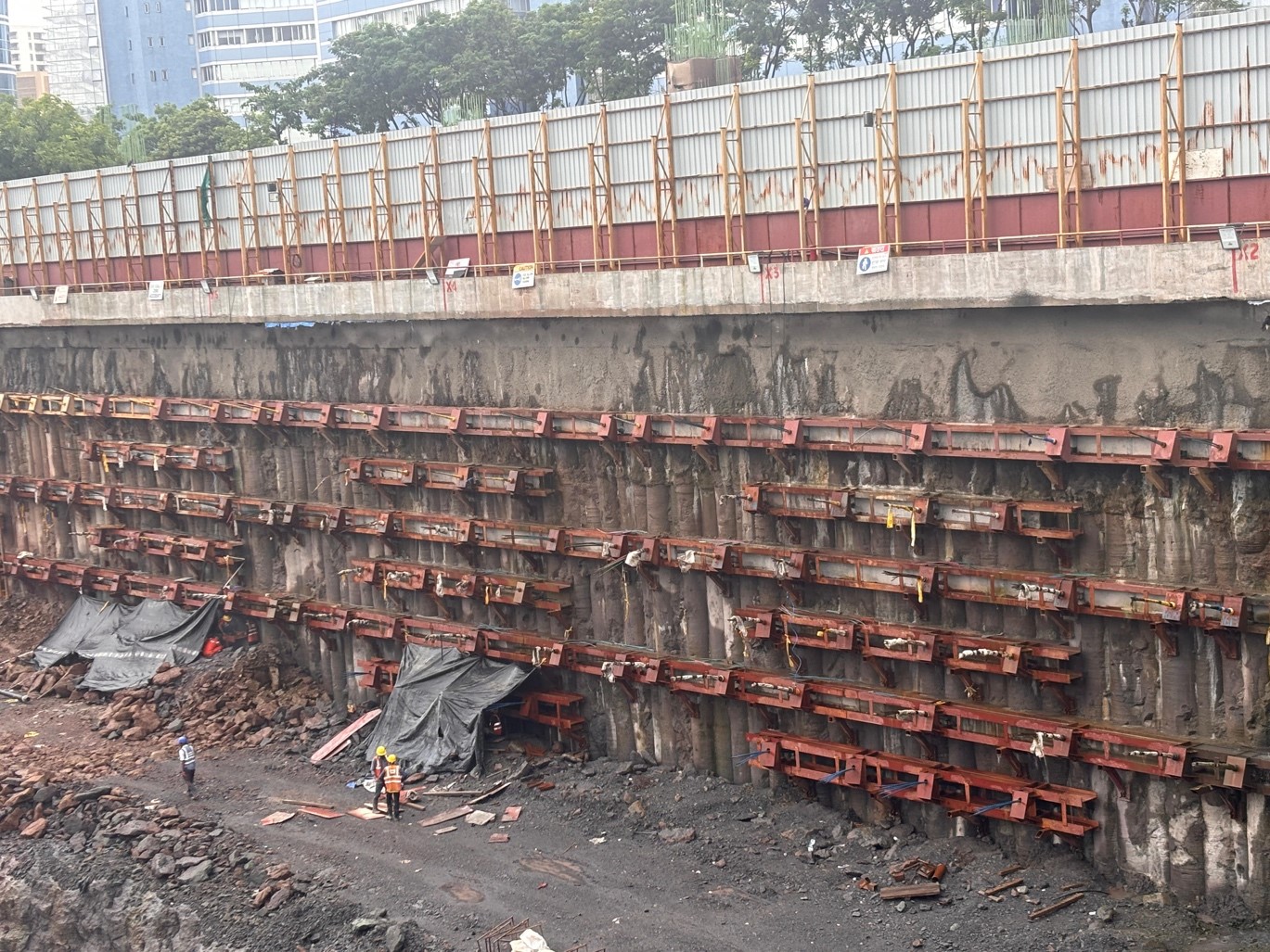
Figure 7: Soil Anchor and Waler at ILFS Station Side
The design and spacing of the soil anchors and walers adjacent to the ILFS station was different from the other locations, due to additional load coming from the pier of the ILFS Piers. The Spacing and angle also changed to accommodate the ILFS piers in between the soil anchors. Both the anchor arrangement are shown below in the pictures
The above image shows various stages of the installation of secant piles, soil anchors, and walers:
- Drilling the Secant Pile Using a Drilling Rig: Drilling depth goes up to 28-30 meters in the first layer, with the depth reducing in subsequent layers.
- Installation of Soil Anchors and Grouting: Soil anchors are installed and grouted with cement grout, and they become ready for stressing once the grout strength of 30 MPa is achieved.
- Fabrication of Walers: Waler fabrication is done in parallel at the fabrication yard.
- Installation of Walers: Walers are installed, and the remaining welding is carried out, including the fixing of A-frames and brackets.
- Packing Concrete Behind the Walers: It is necessary to provide an even surface above the secant piles. In this case, M-35 grade packing concrete has been used.
- Stressing of Anchors: Finally, stressing is done. Before locking the anchors, all the anchors are stressed to 10% beyond the design load. For example, if the design capacity is 400 kN, the anchor is stressed to 440 kN and checked for working capacity at this load. Locking is done at lesser load. It is assumed that the design load shall be achieved as the secant pile deflects.
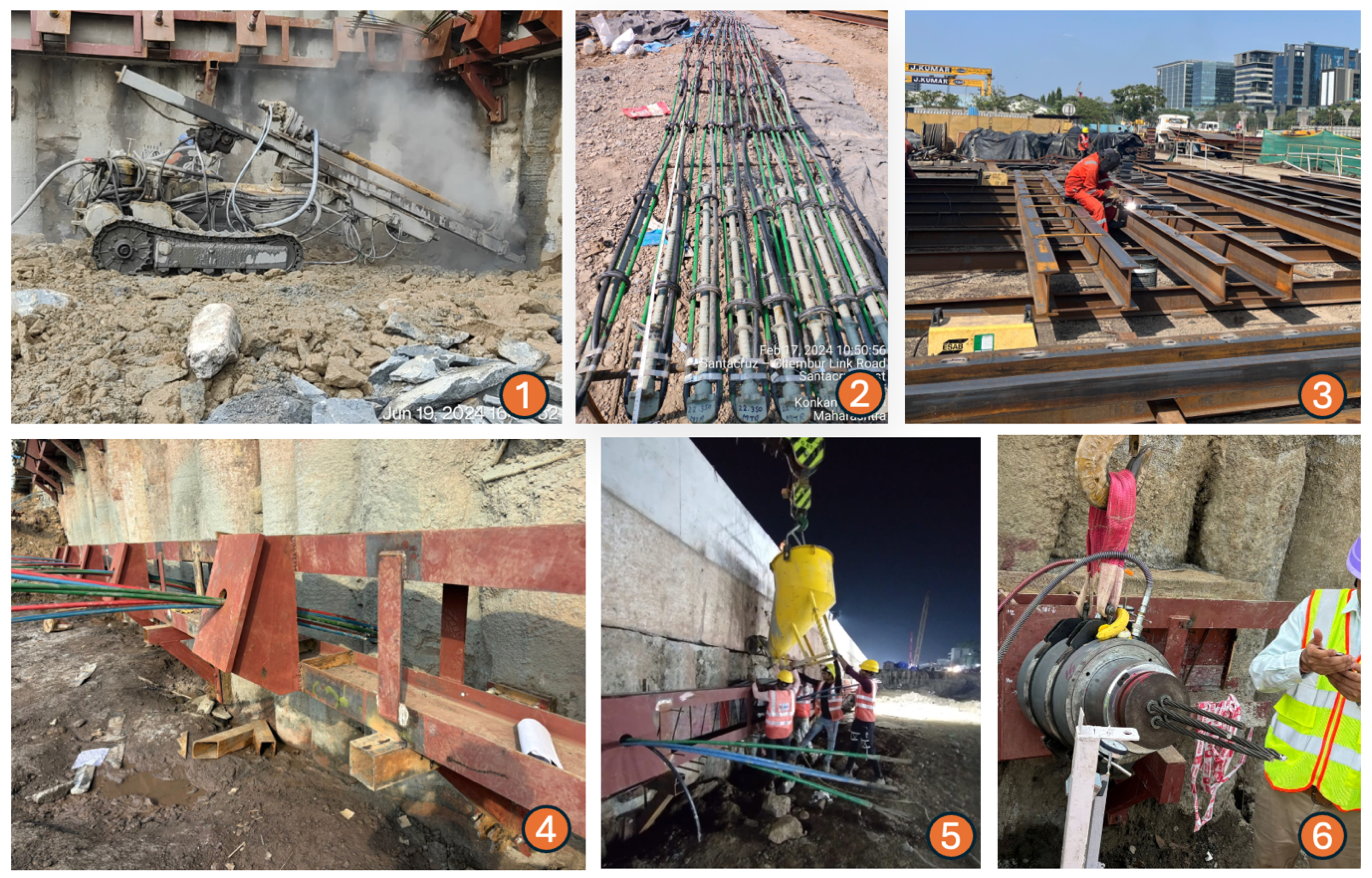
Figure 8: Process of Installation of Soil Anchor and Waler
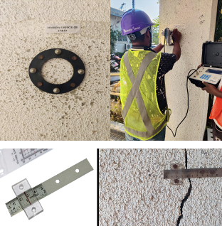
Figure 9: Settlement Marker, and Crack meter
Instrumentation begins with a building condition survey, identifying critical structures and subsequently monitoring them. Risks manifest in two ways: nearby buildings may experience differential settlement, or the ground support system may deviate from its design parameters, exhibiting excessive deflection.
To address these risks, specific instruments are employed. Sensors such as inclinometers and piezometers are used alongside physical markers like ground settlement markers and optical targets. Contractors and engineers regularly verify readings, comparing them with historical data. Additionally, real-time data from critical locations is monitored 24/7 from a central control room.
The secant piles are designed to limit the maximum ground movement of existing buildings (located 50 meters from the face of excavation) to 10 mm or 0.5% of the excavation height, whichever is lower. If the ground movement exceeds this value, actions are taken to limit the permissible strain in the building. Therefore, in-service monitoring of the anchors is essential.
Several factors can be monitored to track the performance of the anchors, including:
- Measurement of the inclination of the piles
- Changes in the force of the prestressed anchors
- Settlement of nearby ground
- Changes in the water table due to seepage or other reasons
Various instruments are available for monitoring these parameters, ensuring that the performance of the ground support system remains within the design specifications and that any deviations are promptly addressed.
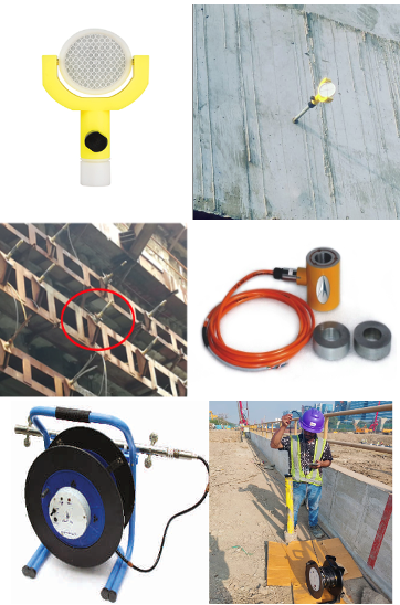
Figure 10: Prism, Load Cell, Inclinometer ( Top to Bottom)
TABLE CATEGORISING INSTRUMENTS
| On Site | Influence Zone | |
|---|---|---|
| Manual measurement | Prism | Building Settlement marker, Crack Meter |
| Sensor based | Inclinometer, Piezometer, Load Cell, Extensometer | Ground Settlement Marker |
A table indicating parameters being monitored in the excavated area and frequency of measurement,
TABLE SHOWING DETAILS OF INSTRUMENTATION
| SN | Important Instrument | Total Nos | Location | Spacing | Frequency of measurement (During/After Excavation) |
|||
|---|---|---|---|---|---|---|---|---|
| Prior to Excavation | During Excavation | Backfilling | After Backfilling | |||||
| 1 | Ground and Pavement Settlement Marker | 372 | Station Periphery | 25m | Weekly | Daily | Weekly | Monthly |
| 2 | Standpipe Piezometer | 20 | On both sides of Station at Ground level | 100m | Weekly | Daily | Weekly | Monthly |
| 3 | Magnetic extensometer in soil | 14 | On Ground Level | At ends of station | Weekly | Daily | Weekly | Monthly |
| 4 | Inclinometer in secant pile | 88 | in secant pile | 25m | Weekly | Daily | Weekly | Monthly |
| 5 | Load Cell | 244 | On Walers | as per drawing | Weekly | Daily | Weekly | Monthly |
| 6 | Stain Gauge | 34 | on Struts | as per drawing | Weekly | Daily | Weekly | Monthly |
| 7 | 3D Optical Targets | 845 | On capping beam and secant pile | as per drawing | Weekly | Daily | Weekly | Monthly |
The environment is a major concern when it comes to excavation activities, as these processes generate significant air and noise pollution. In recent years, air quality in metropolitan cities has notably degraded.
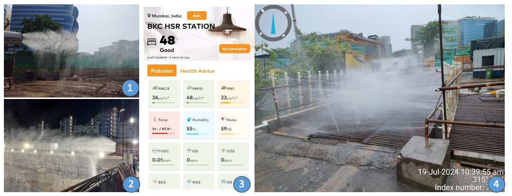
Figure 11: 1& 2: Mist Gun, 3: AQI monitoring on mobile, 4: Wheel Wash
Located in the heart of the city, the Bandra Kurla Complex (BKC) adheres to stringent environmental norms to mitigate these impacts. Excavation activities produce substantial amounts of dust, contributing to air pollution. To counteract this, mist guns are employed, which use fine water mist to suppress the dust generated during excavation. Additionally, continuous sprinkling of water on earthen tracks and covering earth heaps with tarpaulins are standard practices to minimize dust dispersal. Noise pollution is another challenge due to the ongoing piling and excavation work. To address this, 5-meter-high barriers are erected around the work area, helping to reduce the noise impact on the surrounding environment.
Furthermore, live monitoring of the Air Quality Index (AQI) is conducted at the site to ensure that the air quality remains better than in nearby areas. These combined efforts aim to minimize the environmental footprint of the excavation activities while maintaining compliance with environmental standards.
The experiences and methodologies applied in the excavation and construction of the BKC station for the Mumbai-Ahmedabad High-Speed Rail project offer valuable insights for similar projects across Indian Railways. Deep excavation, often required in doubling works or bridge rebuilding projects, poses significant challenges in terms of environmental impact and structural integrity.
By adhering to stringent environmental norms and employing innovative solutions such as mist guns, continuous water sprinkling, and noise barriers, the BKC project demonstrates effective strategies for mitigating air and noise pollution. Real-time monitoring of the Air Quality Index (AQI) further ensures that environmental standards are met consistently.
The comprehensive ground support system, which includes secant piles, soil anchors, and walers, ensures the stability and safety of nearby structures. Full-scale trial anchors and rigorous instrumentation, such as inclinometers and piezometers, play a crucial role in monitoring and maintaining the performance of the support system.
These practices underscore the importance of meticulous planning, innovative engineering, and continuous monitoring in managing the complexities of deep excavation. The lessons learned from the BKC station project can be effectively applied to future projects within Indian Railways, ensuring enhanced safety, environmental protection, and structural integrity. This approach not only supports sustainable infrastructure development but also sets a benchmark for engineering excellence in challenging urban environments.


