

By Shri Rajesh Agarwal, C.P.M.-III, NHSRCL
By Shri Satya Ranjan Acharya, Dy. C.P.M., NHSRCL
By Shri Romank Yadav, Jr. Manager, NHSRCL
Abstract: Mumbai Ahmedabad High-Speed Rail (MAHSR) project is one of the most ambitious rail project taken up by GOI. It is aimed to provide better connectivity between two major cities of western India with 12 stops in between. High speed rail is planned to cater the upcoming requirement of economic and population boom in the region. The project is being implemented with the technological help of Japan and is having approximately 92% elevated structure and remaining 8% as tunnel or on grade. To withstand such tremendous loads of a train moving at staggering speed of 320 kmph, large steel girder spans were adopted at the crossings. The span of these steel girders are ranging between 60 m to 130 m for single span and average weight is 11-15 MT per meter length. Steel bridges were used in form of open web girders (OWG) and fabricated in different parts on India in RDSO approved workshops. The girders were transported to the site location in parts and assembled using TTHSB (Tor shear type high strength bolt) in connections. Case study is being conducted for the use of TTHSB bolts in 100m span Open Web Through Gider known as GAD 31.
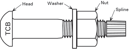
Figure 1: TTHSB fastener assembly
The whole project has been divided into various packages based on the type of structure and length of the stretch. The MAHSR alignment is crossing the existing railway lines and National highways at few locations. Such crossings have been designed as special bridges. A total 5 nos. of special bridges were located between Ahmedabad to Vadodara, and these were awarded as a separate package under the title P1C. The details of the bridges are as follow.
Table 1: List of Bridges in Package P1C
| S. No | GAD No. | Type of Crossing | Span Configuration |
|---|---|---|---|
| Girder Type | |||
| 1 | 1967 | Mumbai-Delhi Expressway NE-4 | 100+300 STEEL TRUSS |
| 2 | 28 | Railway | 60 STEEL TRUSS |
| 3 | 31 | Railway | 100 STEEL TRUSS |
| 4 | 32 | NH 48 | 100+100 STEEL TRUSS |
| 5 | 33 | NH 48 | 40+65+65+40 PSC |
This case study covers the details i.e. materials used in manufacturing, mechanical properties, installation process, advantages etc. about TTHSB and the usage of same in MAHSR project.
TTHSB (Tor shear type high strength bolt), are a type of high- grade bolt that can be preloaded by a tightening process that is carried out entirely at the threaded end (i.e. at the nut or spline end) of the bolt. Consequently, TTHSB’s are usually distinguished by their round heads (rather than hexagonal heads) and splines. TTHSB Grade S10T fasteners are high- strength (10.9), high-ductility (14%) friction grip bolts for use in structural steelwork connections. Their primary advantage (over other types of friction grip bolt) is the ease of preloading the bolts.
The fastener assembly is illustrated in Figure (1), Preloading is carried out by an electrical shear wrench at the threaded end of the bolt i.e., the nut or spline end. At the other end, the head of a TTHSB, Grade S10T is round compared to a hexagonal head for normal bolts, making a TTHSB quite distinctive in appearance
Most bolted connections transfer load ‘in shear’, i.e. the bolt axes are normal to the direction of the load to be transferred. A key choice facing the designer is whether the connection will allow or prevent slip between the joined components.
In a non-preloaded bolt configuration, the applied force is transferred through shear within the bolt shank and through bearing between the bolt shank and the connected layers. For this mechanism to function effectively, there must be relative slippage between the connected layers, as depicted in Figure (2). The benefits of non-preloaded bolting include the requirement for only minimal tightening of the bolts and the absence of a need to mask the faying surfaces (the interfaces) during painting. However, there are scenarios where such slippage is deemed unacceptable.
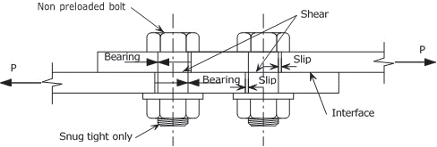
Figure 2: Non Preloaded bolt arrangement
Preloaded bolted joints, commonly referred to as friction grip joints, transfer force in a distinct manner. The load is transmitted through frictional resistance between the contact surfaces of the connected layers, as demonstrated in Figure (3) for a joint using TTHSBs. This contact surface is termed as an interface or faying surface. The frictional resistance is established by subjecting the bolt to significant tension during preloading, effectively clamping the layers together in compression.
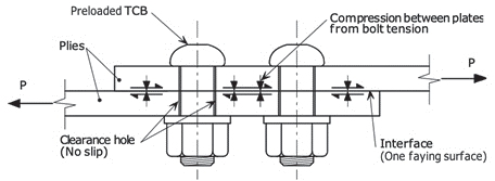
Figure 3: Preloaded bolt connection
| Sr. No. | Description | Characteristics | Frequency | Acceptance Criteria | Reference Document |
|---|---|---|---|---|---|
| 1 | Raw Material | Chemical Composition | Each size / lot | Bolt : C 0.25-0.55, S 0.025 Max., P 0.025 Max. Nut : C 0.58 Max, Mn 0.30 Min. P 0.048 Max, S 0.058 Max. Washer : C0.4-0.5, Mn 0.60-0.90, Si 0.05-0.35, S 0.040 Max, P 0.040 Max. |
As per EN ISO:898-1 |
| 2 | Mechanical Properties | For Bolt 1.Spectro Analysis 2. Tensile strength 3. Yield Strength 4. Elongation 5. Reduction of Area 6. Hardness 7. Decarburization Check 8. Surface Integrity For Nut 1. Spectro Analysis 2. Hardness 3. Proof Load For Washer 1. Spectro Analysis 2. Hardness |
Each size / lot |
TC Bolt As per BS EN 14399-10 & EN ISO:898-1 Chamfered Washer As per |
Figure 4: Inspection Test Plan for TTHSB
| Grade of Bolt | Minimum Tensile(breaking) load(kN) | Hardness | ||||||
|---|---|---|---|---|---|---|---|---|
| Normal size of thread | ||||||||
| M 12 | M 16 | M 20 | M 22 | M 24 | M 27 | M 30 | ||
| S10T | 85 | 157 | 245 | 303 | 353 | 459 | 561 | HRC 27-38 |
Figure 5: Minimum breaking loads for full size TCBs Grade S10T
The preliminary test for axial tension forces was carried out for five bolt sets, sampled at random from each production lot to be used in a day. The average axial tension forces for tightening shall conform to Table Below-
| Nominal diameter | Bolt Temp (10 C to 30 C) | Other Temp (0- 10, 30-50 C) |
Std Deviation of Axial force |
| M20 | 172-202 | 167-211 | 9.5 or less |
| M22 | 212-249 | 207-261 | 11.5 or less |
| M24 | 247-290 | 241-304 | 13.5 or less |
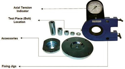
Figure 6: TTHSB Axial tension testing device
This device is used at site to check the axial tension forces in the samples. The device can be mounted in any suitable beam at site and samples are taken from the lot and different sizes which are to be used on that day in field.
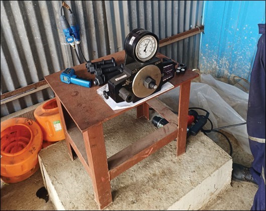
Figure 7: Test setup at site to conduct preliminary test
It is ensured that the connection is properly fitted and assembled and in addition, all the bolts in the joint are snug tight prior to commencing of preloading.
- Slide the inner socket over the bolt spline and the outer socket over the nut As shown in figure (8). Switch on the electric power supply to the wrench. The wrench applies a torque to the nut, via the outer socket, and reacts against the spline, via the inner socket. The nut rotates, while the bolt does not turn. When the torque reaches a sufficiently high level the spline shears off at the break neck (or grove).
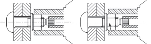
Figure 8: Placing of Torque machine and Rotation of Torque wrench
- When the spline has sheared off pull back on the wrench until the outer socket is no longer engaging the nut. The bolt spline is retained by the inner socket and can be discarded by engaging the small trigger on the wrench handle. To inspect the bolt – after tightening or in the future – merely check that the spline has been sheared off.
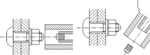
Figure 9: Breaking of Spline and discarding of spline
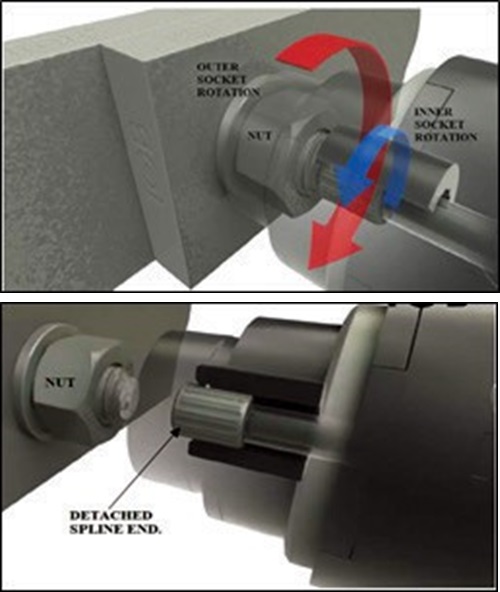
Figure 10: Internal Mechanism of Wrench
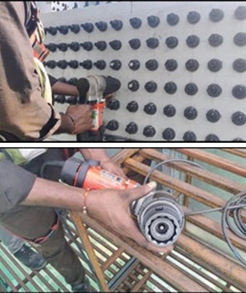
Figure 11: Actual Site photographs
The bolts need to be tightened in a certain sequence on the girder to minimize secondary induced stresses on the assembly. Generally, the sequence followed is middle to outer, connections lying on the middle nodes are tightened first and the adjoining node connections on the both sides of middle node are tightened thereafter. The method is followed till the end node of girders is tightened. Same sequential method is followed while tightening in each splice plates, where middle bolts are tightened first. Figure (12) and (13) depict the sequential tightening.
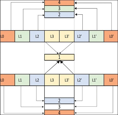
Figure 12: Sequence of Tightening in Girder
Figure 13: Sequence of Tightening in Each Splice plate
After the 1st stage of tightening (Snug tight) the bolts are marked by a straight line passing through washer, nut and bolt using white marker. This line is used to determine the proper tightening of bolts after the 2nd stage of tightening.
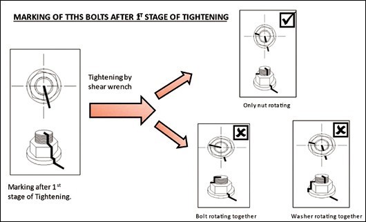
Figure 14: Diagram showing the proper marking and rotation of bolts
As shown in above figure, the marked bolts are tightened using power-wrench. The ideal result after tightening is rotation of nuts only. Rotation of bolts or washer from its original position is not preferable as it depicts improper or inadequate tightening of TTHSB. Following measures shall be taken to ensure the TTHSB tightening in correct and appropriate manner.
- All the surfaces should be cleaned properly before commencement of final tightening.
- Washer must be installed correctly and proper contact area between washer and plate surface must be ensured.
- Sequence of tightening should be strictly followed in each splice plate.
- Tightening operation should be avoided in rainy weather and if at all necessary, proper shade must be installed to cover complete area of operation during rain.
Slipping of TTHSB should be avoided in all the cases as slipped TTHSB will not take full design load in its service period.
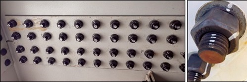
Figure 15: Correct tightening of TTHSB
In nutshell, the TTHSB (Tor Shear type high-strength bolt) stands out as a superior fastening solution in various applications. Due to the heavy preload, the tension across the structure is evenly distributed, and there is no bolt relaxation because no torsional shear is induced during tightening. Its design offers unparalleled ease of use, simplifies installation process and reduces the likelihood of errors. TTHSB provides simple visual inspection for Quality Control as once the spline (pin tail) has sheared off, the correct tension has been achieved which can be checked through a quick visual inspection. It imparts consistent reliable friction grip strength in connections in compare to other preloaded bolts which provides prolonged durability and reliability in service period and makes it cost efficient choice as TTHSB only requires one person for installation with prebuilt functionalities to determine the tensioning required to hold the structure together which reduces installation cost. Further, these bolts are preloaded and involve light weight installation tools decreasing worker fatigue and ensuring no risk of HAVS (hand- arm vibration syndrome).
References:
- JSS II 09-2015, sets of tor-shear type high strength bolt, hexagon nut and plain washer for structural joints.
- DIN EN 14399-10, High-strength structural bolting assemblies in preloading.
- INTERNATIONAL STANDARD ISO 898-01, Mechanical properties of fasteners made of carbon steel and alloy steel.
- EN 14399-06, High-strength structural bolting assemblies for preloading - Part 6: Plain chamfered washers.
Disclaimer:
The following case study is provided for educational and informational purposes only. The views, opinions, and analyses presented in this case study are solely those of the author(s) and/or the organization(s) involved. Any resemblance to actual persons, organizations, situations, or events is purely coincidental. The information contained in this case study is based on the data available at the time of its creation and may not reflect the current status of the subject matter.