

Location: Near Bharuch (Gujarat)
Span: 21 X 60 m (3X60 m Continuous span)
Diameter (outer dia): 10 m
Diameter (Inner dia): 7m & 7.6 m
Steining Thickness: 1.2 m & 1.5 m
Depth: 51 to 77 m
Scour Level: -19 m to -32 m
Founding Level: -36.00 to -70.0 m
By Shri Akshaya Kumar, Chief Project Manager, NHSRCL
Abstract: Well foundations are one of the oldest, yet most effective foundation types for large-scale Civil structures such as railways, highways, or bridges/viaducts over wide rivers. Though efficient & cost-effective, a usual issue associated with well foundation is the tilting and shifting of wells during the sinking process because of; natural forces such as high river flow and tides and unaccounted soil conditions at the sinking level. Over the past few decades, many methods have been innovated to rectify tilt and shift in well foundations: eccentric grabbing, eccentric loading, pulling, the Kentledge method, etc. This paper depicts an innovative technology of using the Jack-Down Method, apart from pulling back which is a process for tilt and shift correction, in conjunction with the kentledge and eccentric grabbing methods.
Introduction
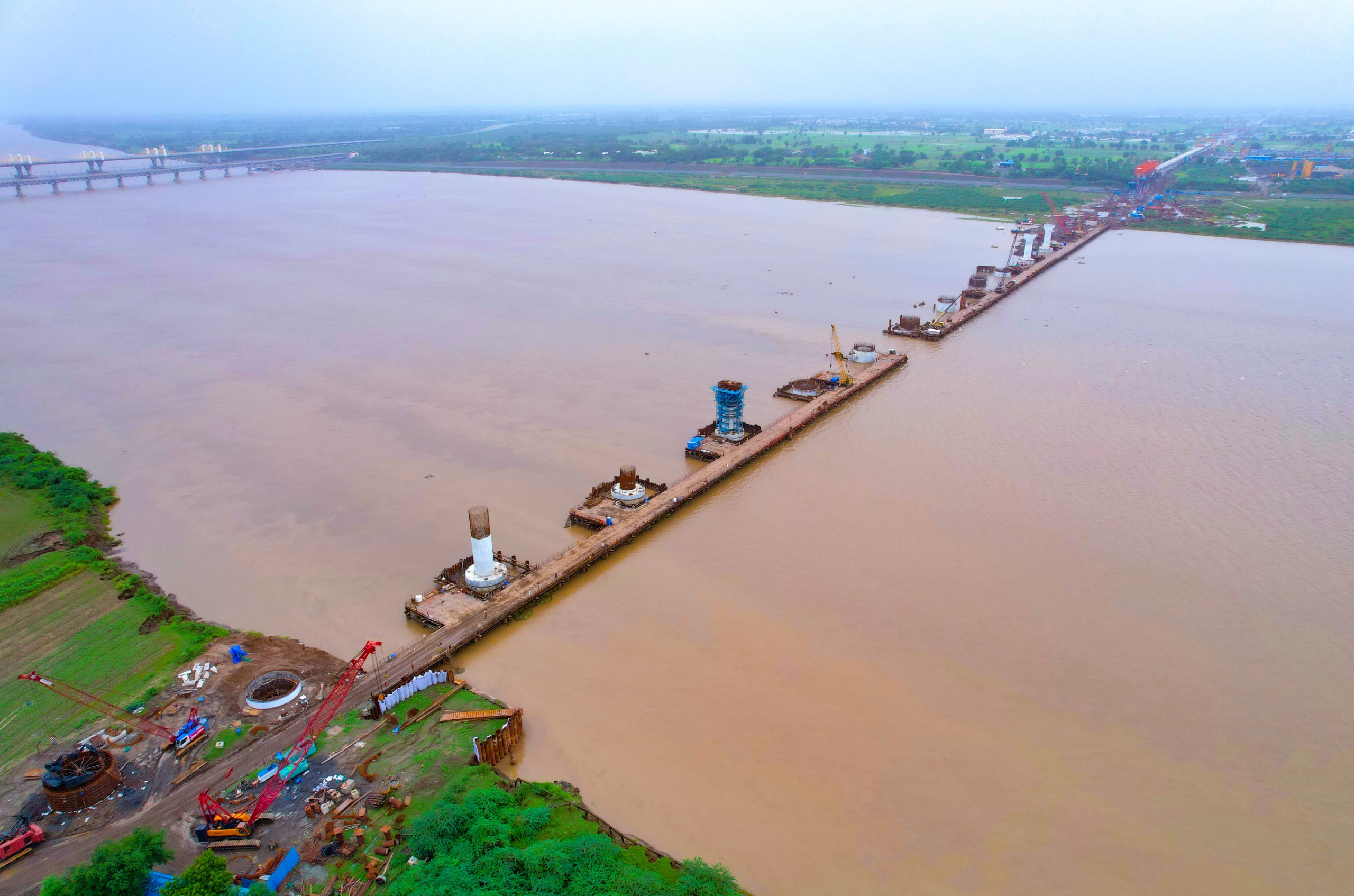
The Narmada Bridge with Well Foundation case study, which is being built for the Mumbai – Ahmedabad High Speed Rail (MAHSR) Project, is the main focus of this report. India’s Bullet Train Project, or MAHSR, is a major infrastructure project that aims to transform rail transportation in India. The project is to build a high-speed (320 km/h) double-track railway line spanning 508 kilometers that will connect Ahmedabad and Mumbai, two of India’s largest cities. The longest river bridge (in Gujarat) in this project, the Narmada Bridge, is being constructed on well foundation.
The 1.26 kilometer long Narmada River Bridge has 22 well foundations.
The bridge’s salient features are as follows:
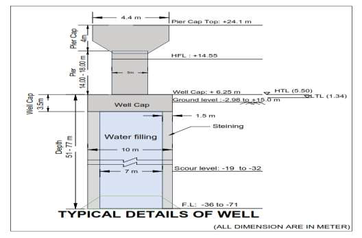
Figure: 1
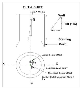
TILT & SHIFT
Tilt of well foundation is deviation from its intended vertical position due to various factors such as uneven soil or rock conditions, obstacles encountered during sinking, or other unforeseen challenges.
Shift in a well foundation refers to the horizontal movement or lateral adjustment of the well structure during its sinking process.
Tilt is measured by checking the levels at fixed gauge mark on both opposite faces along axis of the well. The difference in level will establish the tilt along the axis. It is designated as ratio of difference in level to dia. of well.
The tilt of any well shall not exceed 1 (horizontal) in 100 (vertical), and the shift at the well base shall not be more than 150mm in any resultant direction.
Methods for rectification of excess tilt/shift
Widespread practices in construction industry for rectification of tilt/shift are enlisted, as below:
a) Eccentric grabbing.
b) Eccentric Static Loading (Kentledge)
c) Water Jetting.
d) Pulling of well.
e) Strutting the well.
f) Pushing the well by jacks.
In our present case study of MAHSR Narmada Well Foundation, because of site conditions, the use of the Kentledge method was not delivering acceptable results, as the sinking effort required was much higher than the practically feasible static load on the Kentledge method.
CALCULATION OF SINKING EFFORT
Sinking Effort is required to counter the resistance from:
a) Skin friction on the outer surface of well
b) Buoyancy force
Skin Friction can be calculated as:
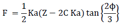
Where F = skin friction in t/m2
Ka =Active earth pressure coefficient
ɸ = Angle of shearing resistance of soil (degrees)
C = Half of unconfined compressive strength.
Z = Depth of foundation below scour level (m)
γ = Density of soil in t/m3.
Skin Friction (F) can be ranged to below values, based upon soil type:
Stiff and soft Clay = 0.73 to 2.93 t/m2
Clay = 4.88 to 19.53 t/m2
Very soft clay = 1.23 to 3.42 t/m2
Dense sand = 3.42 to 6.84 t/m2
Dense gravel = 4.88 to 9.76 t/m2
In our case-study; Considering Sand and clay strata, Skin friction assumed in the calculation is 4.7 t/sqm.
Generally, sinking effort is available from the self-weight of the well only. To reduce skin friction, methods such as air jetting and water jetting are used while sinking.
Sinking effort is available from:
a) Self-weight of well
b) Air/Water jetting (due to reduction of skin friction or buoyancy)
c) External force such as kentledge / Jack down.
Hence, Sinking Effort can be calculated as:
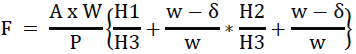
Wherein, f = Average Sinking Effort (t/m2)
A = Cross sectional area of well steining (m2)
W = Weight of steining per meter length of well (t/m)
w = Unit weight of plain concrete (t/m3)
δ = Unit weight of water (t/m3)
P = Perimeter of well (m)
H1 = Height of Well above water (m)
H2 = Height of well below water level & upto bed level (m)
H3 = Depth of well below bed level, where skin friction applies.
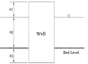
In Limiting condition, H1=0, H2< of H3, hence H2/H3 is neglected,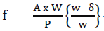
Upon Simplifying above,

Considering,
✓ Buoyancy as: (1000/2500) of weight of well.
✓ Skin Friction = 4.7 T/sqm x Surface area of well.
✓ Air/Water jetting is reducing the requirement of external force by about 50%.
CALCULATION OF REQUIRED EXTERNAL SINKING EFFORT
The sinking effort required for different depths is calculated and summarized as below:
(These calculations are approximate, and no exact theoretical backing is there.)
| Depth (m) | Weight of Steining per meter length of well (W) (MT) | Avg. Sinking Effort (T/m2) | Total Sinking Effort (MT) | Total Skin Friction (MT) | External Force Req. (MT) | Air Jetting / Water Jetting (MT) | Jack Down Force requirement (MT) |
|---|---|---|---|---|---|---|---|
| A | b | C = (4/7)*(W/P) | d = c * Total surface area | e = 4.7 * Total surface area | f = d - e | g = 0.5 * f | h = f - g |
| 10 | 100 | 1.82 | 572 | 1477 | 905 | 452 | 452 |
| 20 | 100 | 1.82 | 1257 | 2954 | 1697 | 849 | 849 |
| 30 | 100 | 1.82 | 1886 | 4431 | 2546 | 1273 | 1273 |
| 40 | 100 | 1.82 | 2514 | 5909 | 3394 | 1697 | 1697 |
| 50 | 100 | 1.82 | 3143 | 7386 | 4243 | 2121 | 2121 |
| 60 | 100 | 1.82 | 3771 | 8863 | 5091 | 2546 | 2546 |
| 70 | 100 | 1.82 | 4400 | 10340 | 5940 | 2970 | 2970 |
* Due to Air Jetting & water jetting, 50% reduction in required external force is assumed.
As can be observed from the above table, the sinking effort required is more than 1000 MT for a depth of more than 30 meters, hence, the conventional Kentledge method seemed insufficient. Therefore, it was decided to use the ‘Jack-Down Method using soil anchors with the Kentledge method’ to achieve the desired sinking efforts.
Air jetting and water jetting arrangement in wells
PROVISION OF AIR JETTING
a) PVC pipe of dia 25mm is being provided horizontally on cover zone to facilitate air jetting air jetting to reduce the skin friction of well surface. This is provided in alternate layer of well steining.
b) The vertical connection for each horizontal layer shall be kept at least 1m above the casted steining to facilitate compressed air.
c) The pipe shall be grouted with pressure grouting by cementitious grout after bottom plugging.
PROVISION OF WATER JETTING
a) Water jetting can be used to facilitate sinking of wells through clay and hard strata.
b) For water jetting required number of steel pipes of 40mm -50 mm dia shall be embedded in the steining of well, spaced evenly around its periphery.
c) The steel pipe shall be kept about 1m above the top of each lift of steining cast.
d) The pipe may be passing through the center of well curb for facilitating water jetting arrangement.
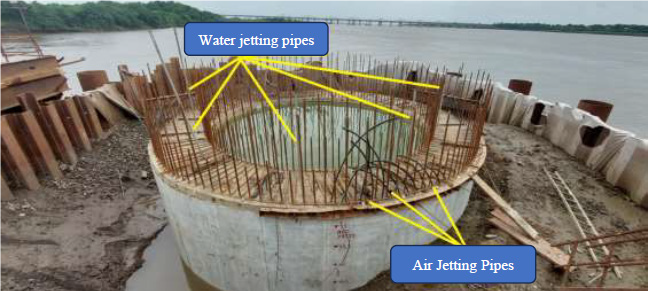
Figure 4 Provision of Air and water jetting arrangement in Wells
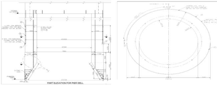
Figure 5 Air Jetting and Water jetting details (typical section) Figure 6 Air and Water jetting details (Typical Plan)
Jack-down method with kentledge & eccentric grabbing for tilt/shift correction
The jacking down method with load up to 1200 MT (or more) on one side of the well (face opposite to tilt) creates a moment and rotates the Well at some point below the bed with support from stiff clay as a fulcrum. (Refer Figures 5,7 &8)
Construction Procedure:
a) The first step is to install ground anchors outside the periphery of the well (Figure 5). The number, location, and depth of ground anchors outside the periphery of the surrounding soil shall be adequate to develop the necessary resisting force through skin friction.
b) The drill holes of the required diameter, along with casings shall be taken down to a depth below the founding level of the well. (Figure 7 & 8)
c) After drilling holes to the required depth, HT strands of adequate diameter and capacity are cut to the desired length and lowered into the holes.
d) The holes shall then be grouted with cement slurry with a non-shrink additive.
e) Heavy-duty pressurization girders fabricated of steel shall be placed over stools resting on the steining of the well against which the hydraulic jacks connected to the ground anchors can exert pressure to push the well down. (Figures 4 &6)
f) The hydraulic jacks shall be of the required capacity as per the required sinking efforts.
g) Pressure on different jacks is exerted in such a manner as to exert external force in the opposite direction of tilt.
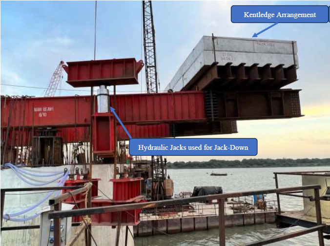
Figure 7 (Jack down with kentledge arrangement)
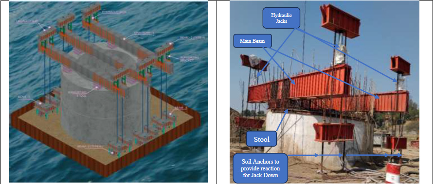
Figure 8 (Isometric view of Jack down arrangement) Figure 9 ( Jack down arrangement )
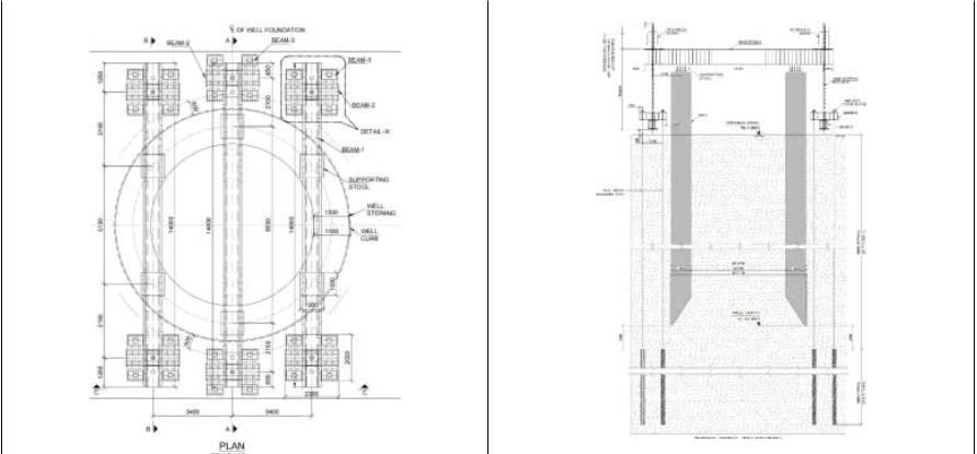
Figure 10 (Jack down schematic diagram) Figure 11 (Jack down Schematic diagram)
Pulling back of well - anchorage from adjoining well for tilt correction
a) Provision of kentledge for the correction of tilt in the opposite direction of tilt.
b) Providing 75mm sling wrap around well to be corrected and same is anchored in nearby well through the pulley. The tilted Well is pulled with a sheave pulley arrangement by taking reaction from the adjoining well.
c) The same sling after passing through pully is connected to rotating drum of mechanical crane which apply load by pulling the sling. (1/4th Load is taken from crane i.e 18T and 3/4th load through the well i.e 54T.) (Figure 9 & 10).
d) Simultaneously sump is made in the opposite direction of tilt so that well can sink and tilt is corrected.
e) After making sump grabbing in outer side will be carried out to reduce the grip length of the well which will help to sink.
f) Air jetting & water jetting are carried out simultaneously as required.
g) When all the above activity is carried out simultaneously tilt of the well got corrected to given tolerance.
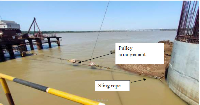
Figure 12 (Pully Arrangement for Tilt correction)
Well, No. 9 had a tilt of 1:25. Using the Kentledge method there was no improvement in tilt.
The pulling of the well by anchoring it with an adjoining well (Figure 9) was planned as explained above, and the results were very encouraging. Within two months, with about 5.0 m of sinking, the tilt got corrected to 1:140 (from 1:25). The date-wise tilt correction is given in the attached table. This method could be adopted as the adjoining well was not disturbed and sunk to an adequate depth so as to take up the reaction force as required.
Tilt Correction with Time for Well No.09
| Date | Actual Sinking (m) | TILT | ||
|---|---|---|---|---|
| Tilt along Y - Axis | Tilt along X - Axis | Resultant Tilt | ||
| 1 in | 1 in | 1 in | ||
| 03/07/2023 | 32.276 | 25 | 244 | 25 |
| 04/07/2023 | 32.426 | 24 | 263 | 24 |
| 19/07/2023 | 32.471 | 24 | 1250 | 24 |
| 20/07/2023 | 32.472 | 24 | 2000 | 24 |
| 20/07/2023 | 32.640 | 28 | 286 | 28 |
| 21/07/2023 | 32.640 | 28 | 286 | 28 |
| 22/07/2023 | 32.687 | 26 | 200 | 26 |
| 24/07/2023 | 32.735 | 26 | 200 | 26 |
| 25/07/2023 | 33.085 | 26 | 179 | 26 |
| 26/07/2023 | 33.189 | 27 | 179 | 27 |
| 27/07/2023 | 33.349 | 29 | 172 | 29 |
| 29/07/2023 | 33.507 | 29 | 172 | 29 |
| 31/07/2023 | 33.670 | 30 | 143 | 29 |
| 01/08/2023 | 33.685 | 30 | 147 | 29 |
| 02/08/2023 | 33.685 | 30 | 147 | 29 |
| 03/08/2023 | 33.685 | 30 | 147 | 29 |
| 05/08/2023 | 33.685 | 30 | 147 | 29 |
| 07/08/2023 | 33.678 | 32 | 145 | 31 |
| 08/08/2023 | 33.689 | 34 | 143 | 33 |
| 09/08/2023 | 33.778 | 116 | 256 | 106 |
| 10/08/2023 | 34.045 | 208 | 455 | 189 |
| 11/08/2023 | 34.038 | 204 | 417 | 183 |
| 25/08/2023 | 34.273 | 137 | 345 | 127 |
| 30/08/2023 | 34.422 | 169 | 370 | 184 |
| 31/08/2023 | 35.436 | 120 | 213 | 105 |
| 01/09/2023 | 35.559 | 172 | 278 | 146 |
| 02/09/2023 | 37.028 | 145 | 286 | 129 |
| 02/09/2023 | 37.597 | 149 | 417 | 140 |
In other wells, due to soil strata, the sinking of wells was not progressing adequately. The jack down method has been adopted to sink through the stiff clay strata. This paper mainly highlights the use of the above two (Jack down and pulling back) methods in the tilt correction of wells. Each method has to be adopted based on the site-specific requirements and feasibility. The method to be adopted must be followed very judiciously based on site specific requirements and suitability.
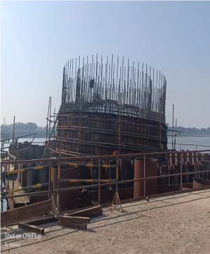
Tilt Correction in Well No. P09 of Narmada Well Foundation (HSR River Bridge)
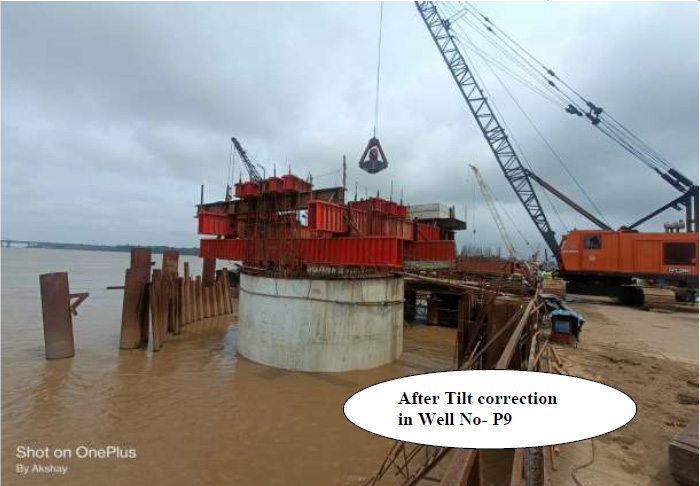
Figure 13 (Well No. 09/Narmada River Bridge HSR)
Conclusion
There are many methods available for tilt correction in wells, like eccentric grabbing, Kentledge, etc. But in the construction of the HSR Narmada Bridge, some special measures have been taken, like the provision of air jetting, and water jetting to improve the sinking of the well. Also, pulling back (with Kentledge) with the help of reaction from adjoining wells has been used for tilt correction very effectively. The use of jack jack-down arrangements for well sinking where adequate sinking effort is not available is an innovative method adopted in the construction of this bridge. This paper discusses only the concepts used for different adopted schemes about well foundations, and the details given are site-specific only and should not be followed at any other site without proper technical analysis and study.
REFERENCES
[1] Doc No. 2005/CE-I/BR-II/8 dated 8th June, 2005 from Sh. RR Jaruhar, Member Engineering Railway Board & Ex-Officio Secretary, Govt. of India, Ministry of Railways, New Delhi-110001.