-Rajneesh Saroj, GM (Civil)/NHSRCL
Synopsys
This technical paper delves into a comparative analysis of steel bridge fabrication methods employed in Japan and traditional practices in India, with a specific focus on the Mumbai Ahmedabad High-Speed Rail (MAHSR) project's adaptation of Japanese techniques. Japan's cutting-edge approach to steel bridge construction, characterized by mechanization, precision, and stringent quality control, is examined in contrast to the conventional methods utilized in India. The paper underlines the remarkable advancements achieved through Japanese methodologies and their potential for setting new industry standards. It also highlights the need for improved precision, traceability, and quality control in traditional Indian practices. By citing the MAHSR project as a notable example of Japanese influence in India, this paper emphasizes the significance of knowledge exchange and technology transfer in advancing the construction industry. Ultimately, it advocates for the adoption of Japanese best practices to elevate the quality and durability of steel bridge construction in India, offering a collaborative path toward innovative and sustainable infrastructure development.
The advent of India's first high-speed rail project, the Mumbai-Ahmedabad High-Speed Rail (MAHSR), brings with it innovative engineering techniques set to revolutionize the construction industry. Steel bridges are a cornerstone of the MAHSR, playing a pivotal role from design and fabrication to bearing systems and painting. This paper explores the dynamic fusion of Japanese bridge fabrication expertise, which MAHSR draws inspiration from, and the traditional methods entrenched in Indian construction practices.
Introduction
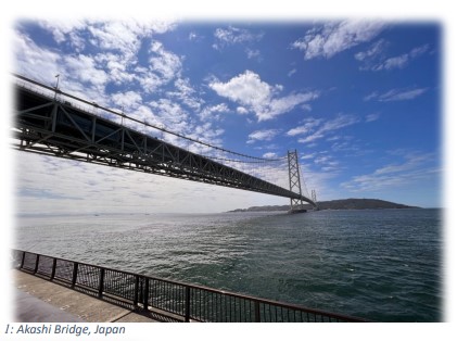
Spanning the globe, bridges like Japan's Akashi Bridge (1997 meters, built in 1998), Tokyo's Rainbow Bridge (798 meters, built in 1993), the Golden Gate Bridge in San Francisco, USA (1280 meters, built in 1937), and India's own Howrah Bridge, Chenab Bridge, and Bogi Wheel Bridge have one common factor – steel.
Recently, India has witnessed a surge in the construction of steel bridges, with remarkable spans of 70 to 100 meters. Whether for Road Over Bridges or Railway bridges, steel structures have gained substantial prominence, exemplified by the awe-inspiring Chenab Bridge. Even within the context of the MAHSR project, continuous spans reaching up to 130+100 meters underscore the growing reliance on steel in bridge construction.
The MAHSR project, India's inaugural high-speed rail endeavor, is a testament to this transformation. Encompassing approximately 70,000 metric tons of steel across 28 bridges and 49 spans, this project uses both simply supported and continuous spans, with the latter extending up to an impressive 130+100 meters.
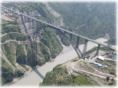
2: Chenab Bridge, India
The bridge fabrication process is distributed across multiple workshops, strategically situated in locations such as Bhuj, Wardha, Durgapur, and Tiruchirappalli, each with a storied history of steel bridge fabrication. However, to meet the exacting standards of the MAHSR project, these workshops had to undergo significant enhancements and rigorous dedication.
While detailing the quest for quality and innovation, this paper also delves into the author's enlightening visit to the SAKAI workshop of IHI near Osaka, Japan. With its monthly production capacity of 3,500 metric tons and complete mechanization, this workshop sets an exceptional benchmark for the quality and precision achievable in bridge fabrication.
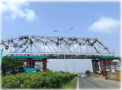
3. GAD 1134 , MAHSR
The ensuing sections of this paper provide an intricate comparison of Japanese fabrication practices and traditional Indian methods, commencing with the pivotal test fabrication process, which serves as a litmus test for workshops adapting to the evolving fabrication techniques and requirements.
Process of Steel Bridge Fabrication
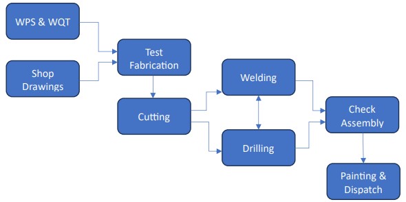
Test Fabrication
Prior to commencing the actual fabrication work, a Test Fabrication (Partial Mock-up) is conducted in each workshop. This process aims to establish an optimized and standardized fabrication work sequence. Test fabrication is performed on the critical nodes of the bridge with a maximum span length, utilizing members of the same size.
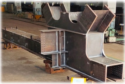
4. Test FabricaCon of CriCcal buHerfly shaped node
Approximately 90 metric tons of steel are allocated for test fabrication, with the steel used in this phase differing from that used in the main fabrication. Full penetration and corner welds in the members are scrutinized through destructive testing, employing a specimen derived from the test fabrication. This specimen is 500mm in length and is cut 100mm away from the weld line. The destructive tests applied to these welds encompass Tensile, Bent, Macro, Charpy impact, and Vickers hardness tests. These examinations serve as an additional layer of quality assurance for both the welding process and the welders themselves.
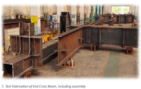
The inspection, examination, and evaluation of the results obtained from the test fabrication process play a pivotal role in determining the suitability and readiness of the workshop for engagement in the main project.
RAW Material
The structural steel, which encompasses steel plates, steel sections, rolled steel, and rolled steel sections used in bridge construction, adheres to several Indian standards, including IS 2062, IS 808, IS 1739, IS 1173, IS:3601, and more. Various steel grades, spanning from E250B0 to E410C, find application in different bridge components.
However, there's an additional requirement for the Short Traverse Reduction Area (STRA) test for plate more than 25mm thick, a tensile test that assesses material ductility in the through-thickness (short transverse) direction. This test is deemed essential due to the use of steel plates with a thickness of up to 50mm in bridge construction.
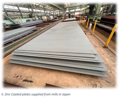
Furthermore, Japan has taken proactive measures by mandating anticorrosive coating on steel plates at the mill itself. After the rolling process, the steel plates undergo blasting and are coated with Zinc Rich paint, providing an extra layer of protection. This initiative extends the workshop's capabilities by allowing for longer storage periods.
Advancement in CNC Cutting
Computerized Numerical Control (CNC) cutting has a well-established presence in various workshops, becoming increasingly commonplace. The key input for CNC machines is the nesting plan, which optimizes steel usage by appropriately marking cutting lines. In the case of the Mumbai-Ahmedabad High-Speed Rail (MAHSR) project, where components featured diverse curvatures and profiles, CNC cutting machines proved invaluable.
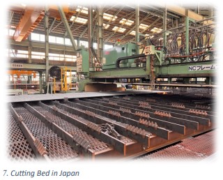
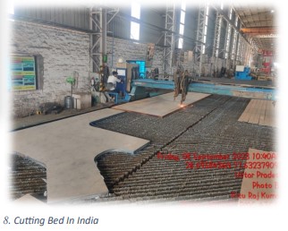
An additional requirement for MAHSR involves the use of an Oxyacetylene flame, in contrast to the traditional LPG flame. This choice is driven by the significantly higher temperature attainable with Oxyacetylene, ranging from 3,480°C to 3,900°C, compared to LPG's 1,980°C to 2,230°C. This not only accelerates cutting but also results in smoother cuts.
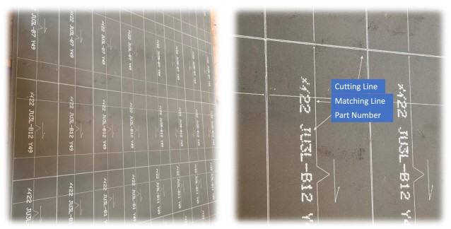
9. Marking on the plate in Japan
Post-cutting distortion, including sweep, is a common concern. In well-controlled processes, distortion typically becomes noticeable only after measurement. Additionally, CNC technology excels at precision cutting for irregular shapes like ovals and circles.
Moreover, Japan leverages CNC for marking cutting lines, part numbers, and fitting lines on plates before cutting, offering advantages in defect identification, such as distortion or sweep. Furthermore, Japanese CNC machines feature iron teeth instead of steel strips as supports on the cutting bed, which incur less damage and are easier to maintain.
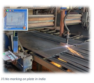
In summary, CNC cutting is widely employed, and the MAHSR project utilizes Oxyacetylene flames for superior results. Post-cutting distortion is addressed with precise measurements, and CNC technology in Japan offers distinct benefits in defect identification and support bed design.
Box Drilling Machine and Match Drilling
The traditional use of jigs and fixtures is gradually giving way to modern machinery. In the traditional approach, plates were cut to meet specific requirements, and drilling was carried out using jigs. However, this method proved to be cumbersome and lacked precision. Drilling holes at the plate stage assumed that there would be no distortion after welding, despite the well known fact that welding often leads to distortion. Consequently, hole alignment and positions would go astray, necessitating correction through various means.
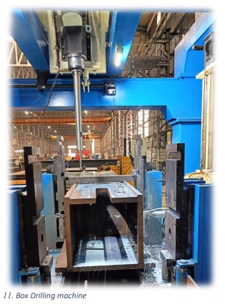
The use of new box drilling machines allows for simultaneous drilling on multiple faces of a member, enabling the maintenance of relationships among groups of holes and reducing the need for post-welding distortion correction. However, dealing with heavy segments on the box drilling machine can be challenging, particularly when the member's size exceeds the working dimensions of the machine. In such cases, the use of jigs for match drilling is adopted.
In the MAHSR project, box drilling machines and, in certain instances, match drilling have been employed during fabrication. In contrast, the Japanese introduced an innovative technique, later incorporated in one of our workshops, which involves drilling holes at the plate stage before cutting. This technique proves useful when achieving almost zero distortion or shrinkage is feasible.
Welder Qualification and Welding
Achieving the desired strength and size in welding has never been a formidable challenge; rather, the focal point of our efforts lay in achieving a finish akin to the standards set in Japan. Our welders often tend to create deeper penetrations and larger weld sizes, which, while fulfilling strength requirements, result in increased consumption of resources such as consumables, electricity, time, and potential grinding work. Various methods can be explored to enhance the final finish, including the careful selection of welding processes and comprehensive training for the welders.
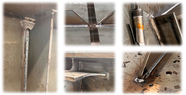
12. Weld Finishes, Japan
There is a multi-layered filtration mechanism for welder qualification which is in addition to the certification per IS 817, requisite experience and training at WRI Trichy/RDSO.
For the Mumbai-Ahmedabad High-Speed Rail (MAHSR) project, it was envisaged to engage an International Expert for Welding and Quality Management, designated as an International Welding Engineer (IWE). In addition to other qualifications, the IWE is required to possess a minimum of 10 years of experience as a supervisor or quality assurance engineer in High-Speed Rail Projects.
The welders undergo examination by International Welding Engineer. The welder is tasked with creating a test piece (T-joint) of specified dimensions with a 6mm fillet weld, conducted in the vertical position. The test piece undergoes visual and fracture testing, with the IWE examining it for cracks, blowholes, slag inclusions, unevenness on the fusion line, and subsequently providing a qualification report. In cases of disqualification, the welder undergoes training, followed by a retest at a later time.
In terms of welder qualification, Japan follows a similar practice. However, one notable difference is that welders in Japan are equipped with respirators to protect them from harmful fumes and gases.
Check Assembly
The check assembly of a steel bridge in a fabrication workshop is a pivotal phase in the construction process, serving as a critical quality assurance step before the bridge components are transported to the construction site.
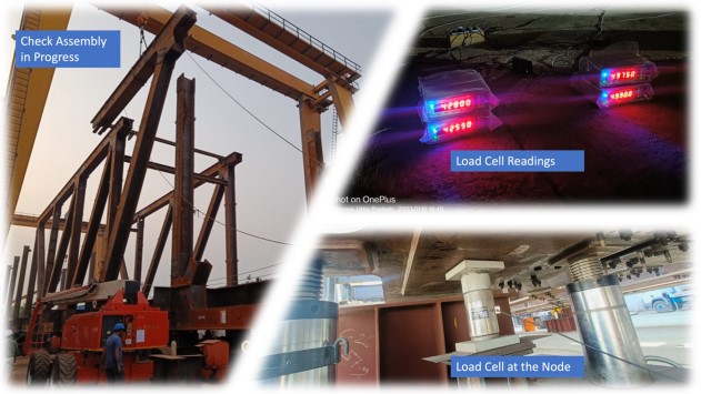
13. Check assembly in Progress
For MAHSR bridges, the check assembly involves placing all the spans on the bearings, with adequate support for the girder at all the nodes. During this phase, the girder undergoes comprehensive checks for various dimensional tolerances, including span length, the distance between the centers of top and bottom chords, alignment, height, member misalignment, hole fairness, bending in members, and camber. Load cells are employed to precisely determine the load transferred at each node. Additionally, a drift and bolting plan for each node and joint is meticulously prepared and handed over to the erection team.
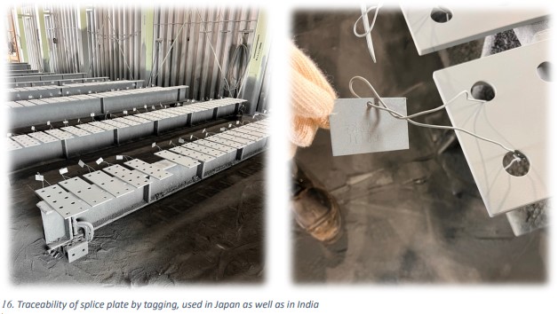
In parallel, during the check assembly, each component is identified and marked to maintain traceability until it reaches the erection site. Notably, traceability, especially for identical members such as splice plates, is of paramount importance to prevent any errors in positioning that could hinder the erection process.
This check assembly significantly differs from the traditional approach, where the girder is supported at the ends and camber is measured.
Blasting and Painting
While steel boasts strength and durability, it is susceptible to corrosion. Therefore, a great deal of care is required post-erection and during the service life of a bridge. In Japan, steel structures adhere to the C5 System of painting, as outlined in the " Japanese Standard Handbook of Corrosion Protection." The steel bridges within the Mumbai-Ahmedabad High-Speed Rail (MAHSR) project in India also utilize this C5 system.
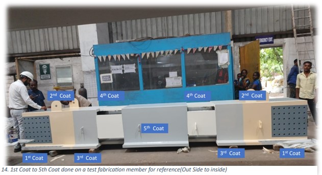
The C5 system, developed over a period of 50 years in Japan with various permutations and combinations, is comprehensively employed there. It significantly differs from the standard painting system recommended in IRS-B1, which involves metallization followed by the application of one coat of etch primer, one coat of zinc chrome primer, and subsequently, two coats of aluminium paint.

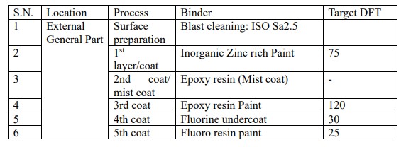
As the name suggests, C5 represents five coats of paint. This process commences with the surface preparation, achieving an SA2.5 grade of ISO specification no 8501-1. It is followed by the application of Inorganic Zinc Rich paint, two coats of Epoxy resin Paint, and two coats of Fluoro resin paint. The aforementioned handbook provides detailed guidance on surface finish, the type of paint, and the required DFT (Dry Film Thickness) for various conditions.
A typical combinations of paint materials and DFT for External General Parts as mentioned in Japanese Standard Handbook of Corrosion Protection (for C5, Spec V), is as under;
Transportation
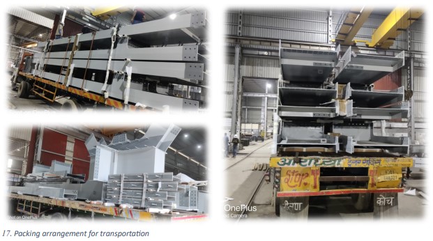
The transportation of girder components can be challenging due to their weight and the risk of damage to the painted surface. To mitigate these challenges, girders are carefully supported to maintain their cross-sectional shape and minimize through-thickness stresses. Additionally, each member is clearly marked to facilitate the erection process.
Conclusion
The preceding discussion offers a comparative insight into distinct approaches towards a shared objective. In an era marked by an economic boom and a resounding push for infrastructure development by the government, the fabrication industry is poised for sustained growth in the coming years. These insights from international best practices can serve as a valuable resource to enhance the productivity of our workshops and ensure the delivery of superior products with stringent quality control measures. The adoption of innovative methodologies, inspired by Japanese excellence, stands as a beacon of promise, heralding a new era of steel bridge fabrication in India.


