
By: Shri D. P. Singh, ED/Design/NHSRCL
Shri Sanjeev Kumar, JGM/Design/NHSRCL
Shri Manoj K Choudary Nalla, DGM/Design/NHSRCL
Shri Rahul Kalra, Sr. Mgr/Design/NHSRCL
Publication: Journal of The Indian National Group of The International Association for Bridge & Structural Engineering
Abstract: Viaducts and Bridges play a pivotal role in transportation infrastructure, serving as critical links between regions and accommodating various modes of transportation, including High-Speed rail (HSR), Railways, Metros, and Highways. The design and construction of bridges for HSR projects differ significantly from other modes of transport. Mumbai Ahmedabad High Speed Rail (MAHSR) is a transformative infrastructure initiative in India that aims to revolutionize the country’s transportation landscape. MAHSR covers a distance of approximately 508 kilometers and will traverse through the states of Maharashtra and Gujarat with a design speed of 350 kmph. Design concepts for structures in MAHSR project are mostly based on Japanese Railway Standards and Guidelines which is a proven technology for Shinkansen High Speed Railway network in Japan. In this paper, one of the unique requirements of MAHSR project i.e., ‘Articulation of Prestressed Concrete (PSC) Box Girder Bridges’ is covered. This paper aims to provide information on bearings and stoppers for MAHSR viaducts and bridges and comparison with conventional system. The paper also touches upon the seismic force assessment for the project.
Keywords: Articulation; Elastomeric Bearings; Steel Stopper; Damper Stopper

Bridges are subjected to a variety of influences that cause displacement of the superstructure and its supports. If these movements are restrained, forces will be generated within the superstructure. To control the development of restraint forces, it has become normal practice to place the superstructure on support bearings, allowing some freedom of relative movement between the deck and supports. In addition to the above, stoppers or retainers are also provided to ensure smooth & continuous operation during service and seismic conditions. The selection and arrangement of bearings and stoppers for use in bridges according to their degree of movement is known as articulation.
In addition to vertical loads (Dead Load, Super Imposed Dead Load, Live Load, etc.), lateral forces in viaducts/bridges are also transferred from the superstructure to the substructure through Bearing system or Bearing and Stopper system. This force transfer plays an important role in ensuring the safety of all elements of the bridge system and the stability of the entire bridge system under various lateral loads. Lateral forces act both in longitudinal direction (along the traffic) and transverse direction (perpendicular to traffic). Various types of lateral forces acting on railway viaducts/bridges are listed below:
- Braking/Traction Forces
- Long Welded Rail Forces
- Impact and Vibration Forces
- Racking Forces/Nosing Forces
- Temperature Forces
- Forces due to creep/shrinkage of PSC girder
- Wind Forces
- Seismic Forces
- Centrifugal Forces due to curvature in track
Simply supported bridges
Lateral force transfer mechanism in PSC box girder bridges of MAHSR is compared to the conventional systems (Elastomeric, POT/PTFE, Metallic bearings) below:
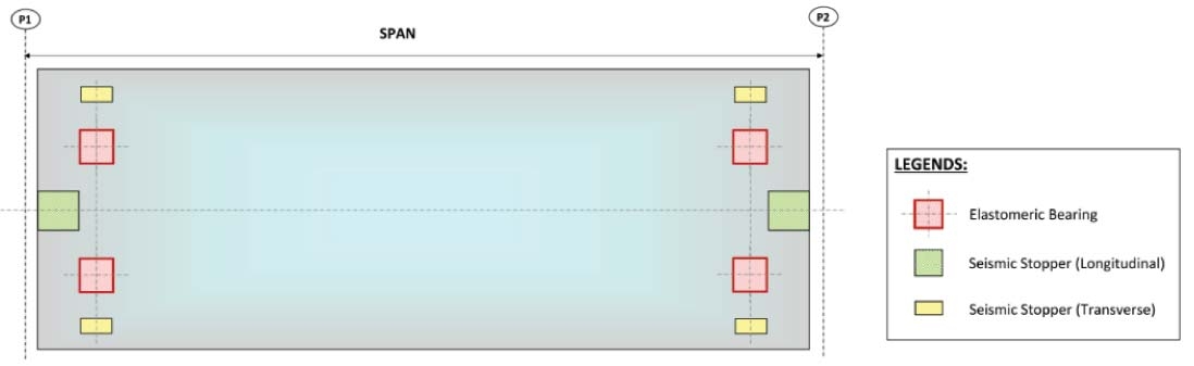
a. Conventional Elastomeric Bearing Force Transfer System
Lateral forces in the longitudinal direction and transverse direction excluding seismic forces are completely transferred to the substructure through elastomeric bearings. In moderate and high seismic prone zones, seismic forces beyond allowable translation (i.e., shear deformation in elastomeric bearings) are transferred to the substructure through a shear key/seismic stopper. In low seismic prone zones, seismic forces are also transferred through elastomeric bearings, whereas stoppers if provided are only to avoid dislodgement of superstructure. Additionally, vertical loads are also transferred through elastomeric bearings. A typical sketch of conventional elastomeric bearing system along with seismic stopper is shown in Fig. 1.
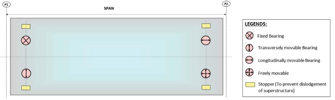
b. Conventional POT-PTFE Bearing Force Transfer System
Lateral forces in both direction including seismic forces are transferred to the substructure through fixed and movable bearings as per the degree of freedom shown in Fig. 2 below:
c. Force Transfer System in MAHSR (Fig. 3)
Articulation system for viaduct and bridges constitute of elastomeric bearings and steel box stoppers. On the fixed end side, elastomeric bearings are designed only for vertical loads from the superstructure, whereas all the lateral forces in longitudinal direction including braking/traction, seismic forces, etc., are transferred to the substructure through steel box stoppers.
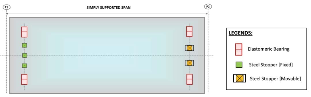
On the movable end side, movement due to lateral forces in the longitudinal direction is allowed in elastomeric bearings and they are designed for shear deformation along with vertical loads from the superstructure.
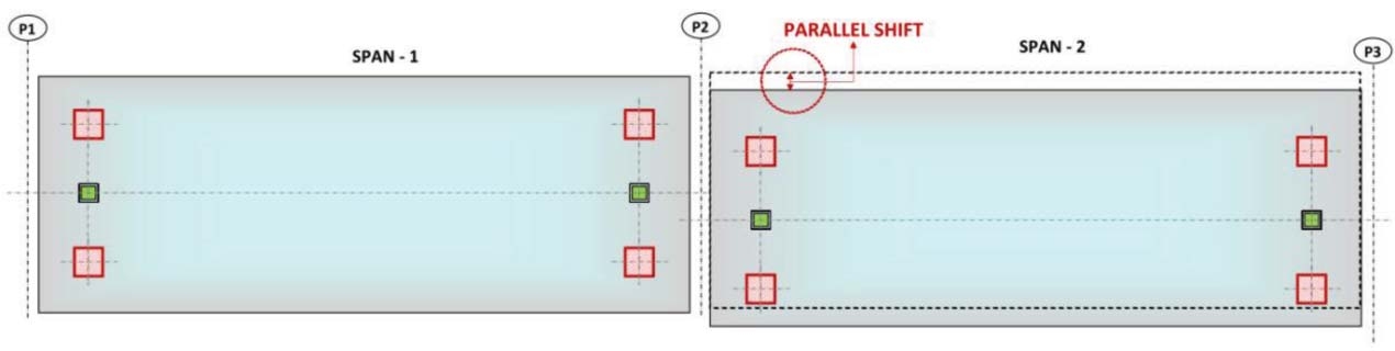
On both fixed and movable sides, all lateral forces in the transverse direction are transferred to the substructure through steel rectangular stoppers only, instead of elastomeric bearings. No gap is kept between the superstructure and steel box stopper in transverse direction. This avoids the parallel shift of superstructure (i.e., stagger) (Fig. 4) which is an important aspect of Running Safety in High Speed Rail (Shinkansen) since the allowable stagger at rail level is very low (limited to 2 mm).
Thus, the main differences between the conventional and MAHSR bridge articulation system are as follows:
- Steel box stoppers on the fixed end side are subjected to longitudinal forces both in service and seismic condition. Thus, segregating the vertical and lateral forces to bearings and stoppers respectively.
- In conventional arrangement, generally separate stoppers are provided to resist forces in longitudinal and transverse directions. Whereas, same steel box stopper (MAHSR) is designed to resist forces in both directions. Additionally, these steel box stoppers act as anti-dislodgement devices.
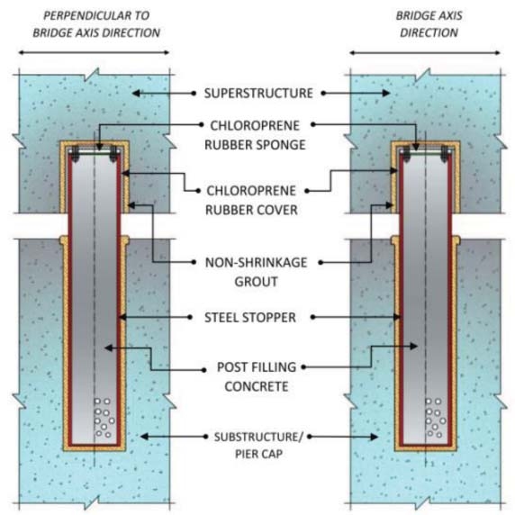
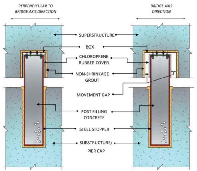
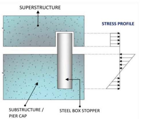
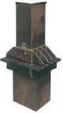
Details of steel box stopper
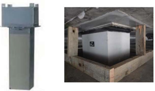
Steel Box Stoppers are hollow square steel sections (rolled/built-up) that are post-filled with concrete. In the fixed side stopper, no movement is allowed between the stopper and superstructure in the longitudinal direction. Whereas, in the movable side stopper, an outer box is provided to ensure the design lateral movement in the longitudinal direction. The fixed and movable side steel stoppers are shown in Fig. 5 and 6 respectively. The Isometric view of steel box stopper and the stress distribution in superstructure and substructure during lateral force transfer through steel box stopper are shown in Fig. 7 and 8 respectively.
Installation of steel stoppers
Steel Box stoppers allow flexibility in the installation process i.e. it can be pre-installed /post-installed.
- Post-Installation: Steel box stoppers are installed in substructure and superstructure through full box-outs in the superstructures after placing the PSC girders on bearings.
- Pre-Installation: Steel Box Stoppers are installed in the substructure in final position prior to launching of the PSC box girders.
Force transfer mechanism in continuous bridges of MAHSR
In continuous bridges of MAHSR, the lateral force transfer mechanism when compared to Conventional systems is as below:
a. Conventional System
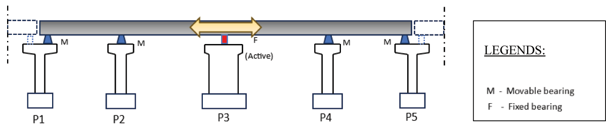
In India, for continuous type of bridges generally POTPTFE along with central metallic guide bearings with seismic restrainers are provided Fig. 9. In traffic direction, all the longitudinal forces arising during the service condition and seismic conditions are taken by the central pier (P3) which results in an increase in the size of the central pier & foundation system, thus limiting the length of continuous bridge
b. MAHSR Damper Stopper System
In MAHSR project, Damper Stoppers are used for continuous bridges which work differently in comparison to conventional system.
The Damper Stopper has a mechanism that allows fixed-movable type of force distribution during service stage (due to shrinkage, creep, braking & tractive, LWR & thermal forces) and distribution of longitudinal forces among all the intermediate piers (all fixed) during earthquakes. This system aids in avoiding the design of single substructure/foundation as Fixed in Continuous bridges.
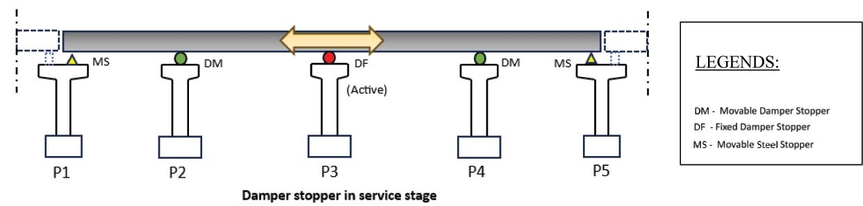
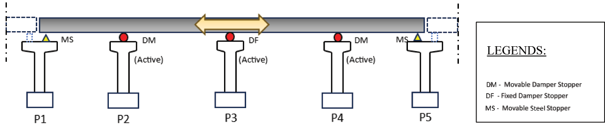
As shown in the Fig. 10, during the service stage, longitudinal forces are transferred through Fixed Damper Stopper (DF) at Pier P3 only whereas in seismic occurrence, the Movable Damper Stopper (DM) at intermediate piers (P2 and P4) also gets locked and share the longitudinal seismic forces along with Fixed Damper Stopper (DF) located over Pier P3 (Fig. 11).
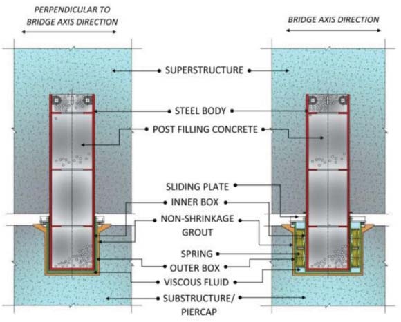
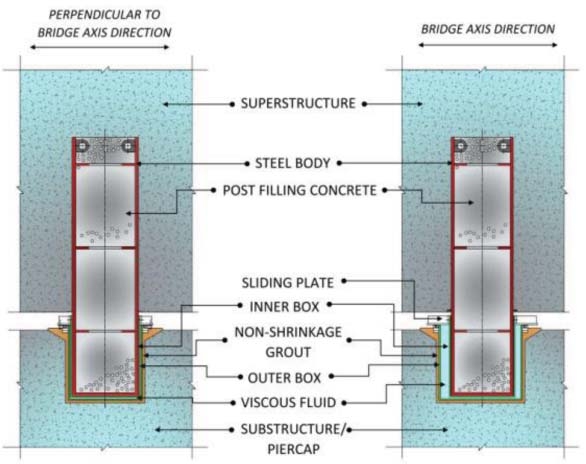
Details Of Damper Stopper
Two types of Damper Stoppers have been used in MAHSR Project i.e., Fixed Damper Stopper and Movable Damper Stopper. The details are mentioned in Figs. 12, 13 and 14. The main body of damper stopper uses square steel section similar to the steel box stopper, however the portion placed in substructure consists of outer and inner box and the gap between these boxes is filled with a viscous fluid. Over the outer and inner box, a sliding plate is placed. In addition to the above, fixed type damper stopper consists of spring leaves which acts under the service condition only (slow-moving loads). Under seismic conditions, the viscous fluid of fixed and movable damper stopper will act and take all the rapid loads (seismic forces). The viscous fluid is velocitydependent and designed to generate the maximum resistance in fast motion, such as during an earthquake. However, the resistance force generated during slow moving motion i.e expansion/contraction of the bridge is small. Viscous fluid is sealed by a sliding plate with stiffeners which is placed on top of the box.
Advantages of damper steel stoppers as compared to conventional systems are:
By using damper stoppers, a long multi-span continuous girder can be constructed in seismic zones.
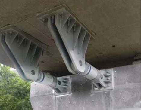
Shock transmission unit (STU) have been used in a few long bridges in India, but damper stopper have added advantages. The damper stoppers also act as seismic restrainer in transverse direction, while in case use of STU (shown in Figure 15), additional seismic restrainer is required in the transverse direction. Due to the presence of spring leaves, Fixed Damper Stopper resists the service loads, whereas in STU system these forces are resisted by bearings. Thus, damper stopper system is a multifunctional system as compared to STU system.
Bearing arrangement in continuous bridges
For continuous bridges, along with damper stopper system, the bearing arrangement system adopted in MAHSR is depicted below.
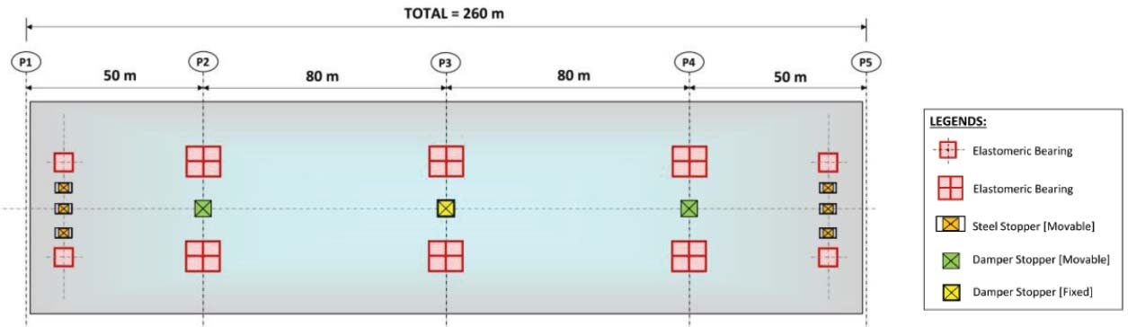
In a 4-span continuous bridge (shown in Fig. 16), only elastomeric bearings are used. These elastomeric bearings are designed to resist vertical loads and shear deformation (at movable locations) along the traffic direction.
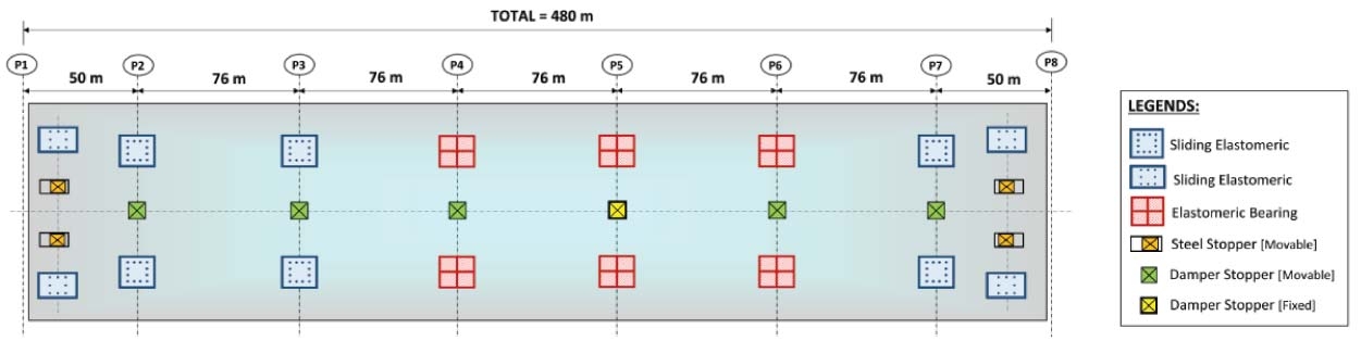
In a 7-span continuous bridge (shown in Fig. 17), elastomeric bearings are used for piers (P4 and P6) adjacent to the Damper Fixed pier (P5). However, to accommodate larger translation due to temperature effects, sliding type of elastomeric bearings are used for other piers (P1, P2, P3, P7 and P8).
Sliding elastomeric bearings
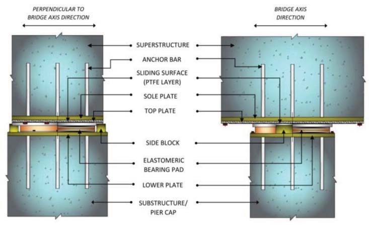
Sliding elastomeric bearing is a type of bearing where vertical loads are transferred from superstructure to substructure through an elastomeric bearing pad, whereas lateral movement of deck in the longitudinal direction is allowed over the PTFE layer placed between the top plate and middle plate shown in the Fig. 18. Side blocks act as a stopper in transverse direction.
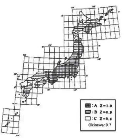
Japan is an earthquake prone country due to the country’s geographical location along the “Pacific Ring of Fire,” where it lies across three tectonic plates, the Pacific Plate under the Pacific Ocean, Eurasian plate and the Philippine Sea Plate. The Seismic Zone factor ‘Z’ which is indicative of the effective peak ground acceleration of a particular zone is shown below for Japan and India. Z ranges from 0,7 to 1,0 in Japan and 0,10 to 0,36 in India.
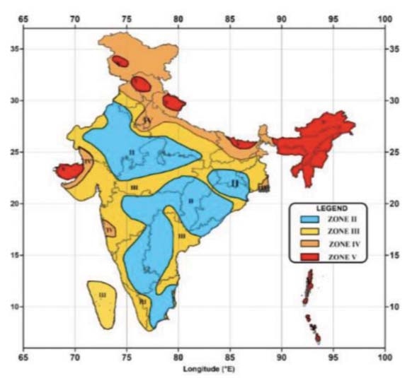
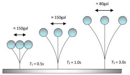
Due to large variation in intensity of Earthquakes and occurrence pattern (indicative of Zone factor ‘Z’) there was a need to develop time history response for MAHSR project. For the calculation of seismic forces for MAHSR project, seismic zone is considered to be Zone III. The maximum response acceleration corresponding to zone III is considered as 0,15 (150gal) and this is set as the target spectrum corresponding to Design Basis Earthquake 0,45 (450gal). The DBE (Design Basis Earthquake) is the earthquake effects which can reasonably be expected to occur at least once during the design life of the structure. It corresponds to an earthquake having 10% probability of being exceeded in 50 years, i.e., 475 year return period. The target spectrum is extended to match the DBE as it is the maximum expected earthquake during the design life as shown in Fig. 21.
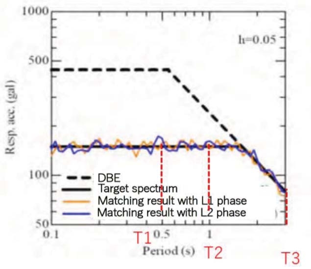
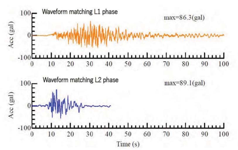
The input waveform (Fig 23) is scaled so that it matches the Target spectrum acceleration as shown in Fig. 21 above.
As per Japanese standards, Restorability means restoring the performance of a structure that has degraded because of accidental loads such as seismic loads, and making continued use of the structure possible. Restorability is specified in view of the degree of difficulty in repairing the structure.
The performance level for restorability is set in consideration of the properties of design actions during the design lifetime. Generally, the following performance levels are set:
Performance level 1: Normally functioning and operable, requiring no repair. This is applied to Level 1 (L1) ground motion. L1 earthquake motion is set as earthquake motion having a probability of occurring several times during the design life at construction site in consideration of regional characteristics in addition to base earthquake motion.
Performance level 2: Function is restorable within a short period of time when repair is required. This is applied to Level 2 (L2) ground motion. L2 earthquake motion should be set as a site-specific earthquake motion based on a strong ground motion prediction method.
The Bearings and Stoppers in the MAHSR project are designed for Performance Level 1 of restorability.
Bridge Articulation play a critical role in design, construction, performance and safety of bridge/viaduct structure. So, the bearings and stopper arrangement shall be judiciously chosen. Steel box stoppers in addition to its multiple roles in force transmission, allow flexibility in installation process i.e. pre installation/post installation, is also cost effective, easy to handle due to being pre-fabricated and easy to use for fast track projects. Further, use of damper stoppers along with elastomeric/sliding bearings allow flexibility to choose the same size of piers and foundation system compared to conventional systems used in India. By using damper stoppers, a long multi-span continuous girder can be constructed in seismic zones without using additional seismic retainers, and also provide good aesthetic appearance to the viaduct/bridge. Because of the multi-functional uses of the steel box stopper and damper stopper, the size of the pier cap is optimized.
Reference
1. SANTO T., SAITO J., and MASUDA K.,
“Transition and Recent Knowledge of Bridge Bearings in Japan”, 15th World Conference on Earthquake Engineering 2012, Vol. 1 of 38, pp 110033 -110041.